How to: Create custom LED Map/Dome lights[Tons of pics]
 03-12-2008, 10:10 PM
#1
Kevlo for President

Thread Starter
iTrader: (36)
Join Date: Dec 2000
Location: Lake Orion, MI
Posts: 35,779
How to: Create custom LED Map/Dome lights[Tons of pics]
This is my howto on how to create custom map/dome lights with premade LED boards. I found the LEDs thanks to AZDAVE on HIDplant.com. Thread here:
http://www.hidplanet.com/forums/viewtopic.php?t=38557
I was never satisfied with the color or the output of the bulbs in the 4th gen map/dome lights so I decided to do my own.
I am NOT liable for anything YOU do to YOUR car so do this at your own RISK.
Tools/Parts:
Phillips Screw Driver
Flat head screw driver
Soldering Iron
Solder
50ohm resistors(or 100ohm) - See http://www.rcaz.com/images/electroni...r_solution.jpg
Led Cluster: http://cgi.ebay.com/Fantastic-Cluste...QQcmdZViewItem
Hot glue gun
Wire strippers/Cutters
Shrink Wrap(optional)
Installation:
Remove the map light by just pulling it down. It will come out easily. Get the boards and glue one board in the middle. Take another board and remove it from its base. Glue this one in next to the first board.
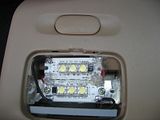
Solder one ground to another.
- Yes I know it looks like **** but I don't want any comments on it
Run the wires through the holes and solder in as shown. The grey wire with the blue stripe is POSITIVE and the solid wire is the NEG.

Daytime pic - no flash
Daytime with cover on.
http://www.hidplanet.com/forums/viewtopic.php?t=38557
I was never satisfied with the color or the output of the bulbs in the 4th gen map/dome lights so I decided to do my own.
I am NOT liable for anything YOU do to YOUR car so do this at your own RISK.
Tools/Parts:
Phillips Screw Driver
Flat head screw driver
Soldering Iron
Solder
50ohm resistors(or 100ohm) - See http://www.rcaz.com/images/electroni...r_solution.jpg
Led Cluster: http://cgi.ebay.com/Fantastic-Cluste...QQcmdZViewItem
Hot glue gun
Wire strippers/Cutters
Shrink Wrap(optional)
Installation:
Remove the map light by just pulling it down. It will come out easily. Get the boards and glue one board in the middle. Take another board and remove it from its base. Glue this one in next to the first board.

Solder one ground to another.
- Yes I know it looks like **** but I don't want any comments on it

Run the wires through the holes and solder in as shown. The grey wire with the blue stripe is POSITIVE and the solid wire is the NEG.

Daytime pic - no flash

Daytime with cover on.
Last edited by Kevlo911; 06-30-2011 at 07:24 PM.
 03-12-2008, 10:10 PM
#2
Kevlo for President
Thread Starter
iTrader: (36)
Join Date: Dec 2000
Location: Lake Orion, MI
Posts: 35,779
Dome light:
Now on to the dome light. Remove the cover on the dome light and then remove the 2 phillips screws holding it in place.
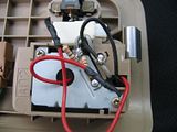
You can mount the leds however you want. I wanted to keep the stock parts in so I did it this way. I cut off one end of the board making sure I didn't cut any traces EXCEPT the ones that connect the (+) and (-) on each side. Be careful when doing this.

This is how I installed the boards. Connect the grounds to eachother and you want to make sure you connect the grounds to the WHITE wire and the white wire ONLY. If you don't you would be able to retain the ON and Door open function. The hot glue also keeps the connections from touching so they wont short out.
Run the wires as shown.

Install like shown. The Grey/blue wire is positive once again.
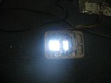
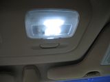
Test just to make sure I wired it properly haha.
PLENTY of output
Now go back and install it in the car...
Now on to the dome light. Remove the cover on the dome light and then remove the 2 phillips screws holding it in place.
You can mount the leds however you want. I wanted to keep the stock parts in so I did it this way. I cut off one end of the board making sure I didn't cut any traces EXCEPT the ones that connect the (+) and (-) on each side. Be careful when doing this.
This is how I installed the boards. Connect the grounds to eachother and you want to make sure you connect the grounds to the WHITE wire and the white wire ONLY. If you don't you would be able to retain the ON and Door open function. The hot glue also keeps the connections from touching so they wont short out.

Run the wires as shown.

Install like shown. The Grey/blue wire is positive once again.

Test just to make sure I wired it properly haha.

PLENTY of output
Now go back and install it in the car...
Last edited by Kevlo911; 06-30-2011 at 07:25 PM.
03-12-2008, 10:11 PM
#3
Kevlo for President
Thread Starter
iTrader: (36)
Join Date: Dec 2000
Location: Lake Orion, MI
Posts: 35,779
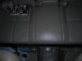
Output pictures:

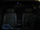
Backseat - map light output.
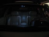
From the outside of the car - map light only.
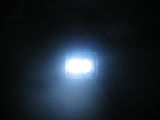
From the sunroof closed - map light only

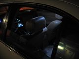
Drivers side front - Dome light only
Next to dome light - dome output
Backseat - map light output.

From the outside of the car - map light only.

From the sunroof closed - map light only

Drivers side front - Dome light only

Next to dome light - dome output
Last edited by Kevlo911; 06-30-2011 at 07:26 PM.
03-12-2008, 10:18 PM
#4
Kevlo for President
Thread Starter
iTrader: (36)
Join Date: Dec 2000
Location: Lake Orion, MI
Posts: 35,779
More output

From front of car - dome only

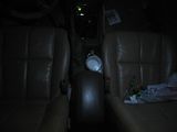
Back seat - map and dome on
From outside the car - map and dome on
From the front of the car - map and dome on

From outside the car - map and dome on

Random shot of my 2 color gauges lol.
This cost me about 10 bucks so I considered it a success.

From front of car - dome only

Back seat - map and dome on

From outside the car - map and dome on

From the front of the car - map and dome on

From outside the car - map and dome on

Random shot of my 2 color gauges lol.
This cost me about 10 bucks so I considered it a success.
Last edited by Kevlo911; 06-30-2011 at 07:27 PM.


 Nice thread kev.
 05-23-2008, 07:00 AM
#10

just ordered 50 3mm white 6000mcd LEDS and going to redo everything, pretty much what you did, cause setup right now is crap and is falling apart. 
where did you get your breadboard by the way? radioshack perhaps?
where did you get your breadboard by the way? radioshack perhaps?
05-23-2008, 07:26 AM
#14

wouldnt have been easy to make the led's a plug and play so you didnt have to splice everything?
are the back of your bread boards adhesive?
good work overall, nice modification
are the back of your bread boards adhesive?
good work overall, nice modification
05-23-2008, 08:07 AM
#16
i just bought some led boards off of an org member im sure it was failry simple to make. its for a 5th gen though.
http://forums.maxima.org/showthread.php?t=543995
http://forums.maxima.org/showthread.php?t=543995
05-23-2008, 08:15 AM
#17
Kevlo for President
Thread Starter
iTrader: (36)
Join Date: Dec 2000
Location: Lake Orion, MI
Posts: 35,779
i just bought some led boards off of an org member im sure it was failry simple to make. its for a 5th gen though.
http://forums.maxima.org/showthread.php?t=543995
http://forums.maxima.org/showthread.php?t=543995
Too much money and too many LEDs.
 05-23-2008, 12:57 PM
#20
 05-23-2008, 01:52 PM
#21
05-24-2008, 06:51 PM
#22
ya, i bought LEDs for cheap and PC Board and did this project a few years back.
kevlo you did a great job. i'll add my pics so people have more reference as well.
 how i did the courtest lights (in the door). you can google up 'led calculator' to figure out what ohm resistors you need depending on how many led's are in your array.
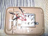
 test fitting of the pc board i cut out in the map light. i had to do some dremeling and use one of the stock screws to hold the pcb in place.

back of the pcb. keep the soldering clean and make sure the contacts are firm. i recommend using flux and running the + and - in opposite directions.

how i put everything together. make sure you have a resistor in there
 the what it looks like in, all ready to go
kevlo you did a great job. i'll add my pics so people have more reference as well.
how i did the courtest lights (in the door). you can google up 'led calculator' to figure out what ohm resistors you need depending on how many led's are in your array. test fitting of the pc board i cut out in the map light. i had to do some dremeling and use one of the stock screws to hold the pcb in place. back of the pcb. keep the soldering clean and make sure the contacts are firm. i recommend using flux and running the + and - in opposite directions.
how i put everything together. make sure you have a resistor in there
the what it looks like in, all ready to go
05-24-2008, 06:53 PM
#23

test fitment of the pcb in the dome light
you know what im too lazy to post the rest of my pics so if you want to check them out on my cardomain here:
http://www.cardomain.com/ride/352601/10
 10-05-2008, 05:46 PM
#26

test fitment of the pcb in the dome light
you know what im too lazy to post the rest of my pics so if you want to check them out on my cardomain here:
http://www.cardomain.com/ride/352601/10
I wired everything series-parallel in groups of three, using a 100 ohm resistor to manage current on each of the series legs. Although not necessary, I also used an LM317T variable voltage regulator (wired with a single sensing resistor so it performs as a current regulator) for the map light and dome light so regardless of the battery voltage they will remain the same brightness. Works pretty well.
Thanks for the photos that got me started on this project!
As an aside, just looking at some of the way people have their LED's wired in an array, I would only expect to see a few hundred hours of lifespan from running them way, WAY over the rated current. Brush up on Ohm's law before you do this, unless you want to have to pull your boards out again. Running 20mA or less should get you a long, long LED life.... much longer than the life of the car.
Last edited by NousDefions; 10-05-2008 at 05:56 PM.

 02-03-2009, 09:27 PM
#29
Junior Member

Join Date: Dec 2008
Posts: 29
Ok so I was making my bulb using this method "http://www.pbase.com/dloftus/led_flashlight_bulb" but i used a 100 ohm resistor instead, the bulb still doesn't work in the car but when I connect it to a 9v battery it works. whats wrong to I a higher number resistor. This is my first try at this so sorry if what im asking is a dumb question.
 02-05-2009, 04:53 AM
#31
Junior Member

Join Date: Jan 2009
Location: Rhode Island
Posts: 21
Nice Project, that was one of the things I didn't like about my car when I bought it. Interior lights are too dim (especially the door ones). If you did the door lights too can we see some pics and also how long did it take to do both lights?
02-05-2009, 05:47 AM
#32
Kevlo for President
Thread Starter
iTrader: (36)
Join Date: Dec 2000
Location: Lake Orion, MI
Posts: 35,779
Ok so I was making my bulb using this method "http://www.pbase.com/dloftus/led_flashlight_bulb" but i used a 100 ohm resistor instead, the bulb still doesn't work in the car but when I connect it to a 9v battery it works. whats wrong to I a higher number resistor. This is my first try at this so sorry if what im asking is a dumb question.
That write up is for 3v? Did you get it up to 12v? I would assume the wireing is backwards if it works with a 9v batt and not the car. Did you try it on the car batt?
02-05-2009, 07:04 AM
#34
Kevlo for President
Thread Starter
iTrader: (36)
Join Date: Dec 2000
Location: Lake Orion, MI
Posts: 35,779
My bad i misread what you are trying to do. If you are using one led, it is not gonna be very bright but. To get the right resistor you need the specs on the led and plugging it into:
http://led.linear1.org/1led.wiz
To get the proper resistor.
http://led.linear1.org/1led.wiz
To get the proper resistor.
Last edited by Kevlo911; 02-05-2009 at 07:09 AM.
 02-06-2009, 08:01 AM
#38
Senior Member

Join Date: May 2007
Location: Boston, MA
Posts: 392
My bad i misread what you are trying to do. If you are using one led, it is not gonna be very bright but. To get the right resistor you need the specs on the led and plugging it into:
http://led.linear1.org/1led.wiz
To get the proper resistor.
http://led.linear1.org/1led.wiz
To get the proper resistor.
EBAY
But I'm still a little confused, even with the calculator.
If I use two of these for the center dome, it will be 16 Leds...so I put the source voltage as 13.4 (car batt)..3.3 forward voltage and 20mA and it says I need 1/4W resistors....12ohm for four leds...
The way the wiring diagram shows it is wiring four leds, to four resistors, but in this case it would be 8 leds to one resistor because of the board...
ARRGHHH am I on the right track here?
