OEM Electrical System Upgrade II of II: BIG THREE, Grounding Kit Big Brother (HOW-TO)
 08-26-2006, 06:10 PM
#1
OEM Electrical System Upgrade II of II: BIG THREE, Grounding Kit Big Brother (HOW-TO)
This is the second section of my electrical system upgrade. You can read the first part, how to upgrade the OEM ground wire, here.
This how-to will be covering the details on how to perform the upgrade known as the 'Big Three'. Essentially, it will yeild the following:
1) Reduced dimming and smaller voltage drops
2) More stable voltage and better current flow
3) Less strain on your vehicle's charging system
The BIG THREE consists of:
(1) Battery negative to chassis
(2) Alternator to battery positive
(3) Engine Block to chassis
...it essentially does the same thing as a conventional grounding kit, however it does so in a different fashion. I am not a big fan of grounding kits as I prefer this method. People will argue this one way or another, but I swear by this. So, let's get started!
TOOLS/SUPPLIES
10mm Socket
12mm Socket
Ratchet
10ft. of 1/0AWG Power Cable
3 1/0AWG Ring Terminals
1 1/0AWG Fuse Terminal w/ 300-amp fuse
STEP I - BATTERY NEGATIVE TO CHASSIS
Simple enough. We are going to be making an attachement from the negative terminal of the battery to the chassis. If you peek behind the battery you will see a good place to plant the wire.
Remove the bolt with your 10mm socket and sand away the spot to bare steel. After that, attach about a 1-ft. length of wire to one of your terminals, crimp, and bolt everything back together.
STEP II - BATTERY POSITIVE TO ALTERNATOR POST
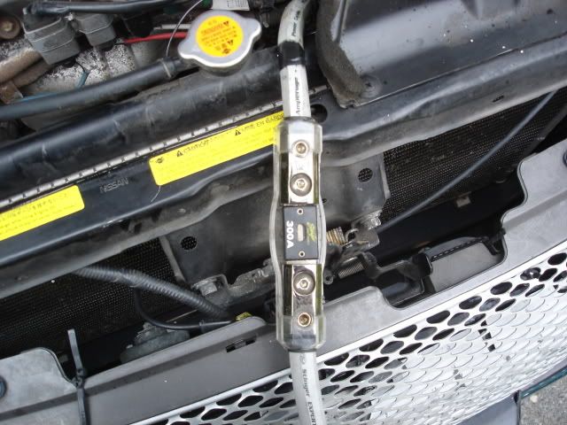
Alright, this one is a bit more tricky. You are going to need about 5ft of wire split into two equal 2.5ft. lengths. We are going to be attaching the wire to the battery positive to a fuse terminal, then fuse terminal to alternator post.
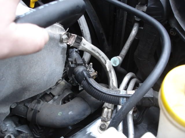
You can find the alternator just to the outside end of the engine block on the passenger side. Look for a rubber boot covering a bolt. That's your alternator post. We'll start there. Remove the bolt using a 12mm socket.
Attach one crimped end of the 1/0AWG wire to the bolt, then screw everything back together.
Take the lead attached to the alt. post and run this to the fuse. Take the other length of wire and run this from the opposite end of the fuse and lead it to the battery. We're almost done![/COLOR]
This how-to will be covering the details on how to perform the upgrade known as the 'Big Three'. Essentially, it will yeild the following:
1) Reduced dimming and smaller voltage drops
2) More stable voltage and better current flow
3) Less strain on your vehicle's charging system
The BIG THREE consists of:
(1) Battery negative to chassis
(2) Alternator to battery positive
(3) Engine Block to chassis
...it essentially does the same thing as a conventional grounding kit, however it does so in a different fashion. I am not a big fan of grounding kits as I prefer this method. People will argue this one way or another, but I swear by this. So, let's get started!
TOOLS/SUPPLIES
10mm Socket
12mm Socket
Ratchet
10ft. of 1/0AWG Power Cable
3 1/0AWG Ring Terminals
1 1/0AWG Fuse Terminal w/ 300-amp fuse
STEP I - BATTERY NEGATIVE TO CHASSIS
Simple enough. We are going to be making an attachement from the negative terminal of the battery to the chassis. If you peek behind the battery you will see a good place to plant the wire.
Remove the bolt with your 10mm socket and sand away the spot to bare steel. After that, attach about a 1-ft. length of wire to one of your terminals, crimp, and bolt everything back together.
STEP II - BATTERY POSITIVE TO ALTERNATOR POST
Alright, this one is a bit more tricky. You are going to need about 5ft of wire split into two equal 2.5ft. lengths. We are going to be attaching the wire to the battery positive to a fuse terminal, then fuse terminal to alternator post.
You can find the alternator just to the outside end of the engine block on the passenger side. Look for a rubber boot covering a bolt. That's your alternator post. We'll start there. Remove the bolt using a 12mm socket.
Attach one crimped end of the 1/0AWG wire to the bolt, then screw everything back together.
Take the lead attached to the alt. post and run this to the fuse. Take the other length of wire and run this from the opposite end of the fuse and lead it to the battery. We're almost done![/COLOR]
Last edited by Metal Maxima; 12-30-2008 at 08:58 PM. Reason: Updated links
 08-26-2006, 06:11 PM
#2
STEP III - ENGINE BLOCK TO CHASSIS
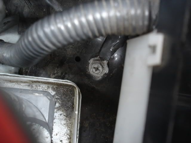
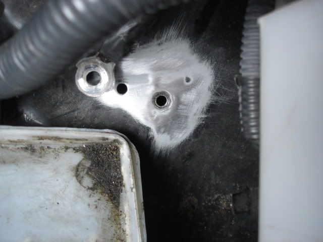
The final step is simple enough. Start off by locating a spot where you want to land the lead on the chassis. I chose an empty bolt hole located by the engine block. Sand away as we have done before.
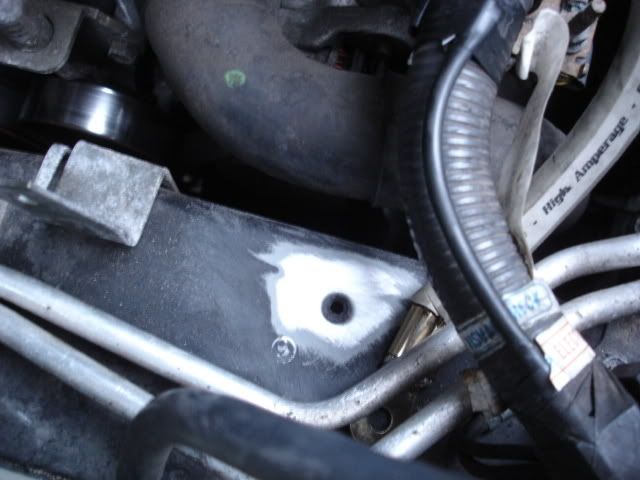
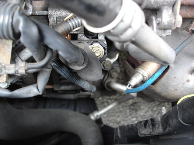
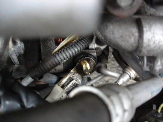
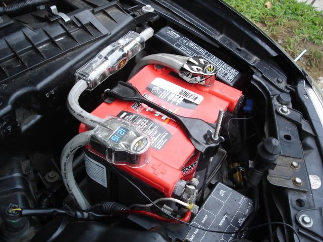
Next, simply ground this to the engine block. I chose one of the 10mm bolts located on the side of the block. You can choose just about anywhere on the block; for instance, you will see two grounding points on top of the block. Golden rule with grounding wires is to keep them as short as possible, so just keep that in mind when doing this...
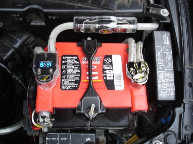
...and now you're done! Here's a shot of the battery when all is said and done...pretty bada'ss if I say so myself!
[/COLOR]
The final step is simple enough. Start off by locating a spot where you want to land the lead on the chassis. I chose an empty bolt hole located by the engine block. Sand away as we have done before.
Next, simply ground this to the engine block. I chose one of the 10mm bolts located on the side of the block. You can choose just about anywhere on the block; for instance, you will see two grounding points on top of the block. Golden rule with grounding wires is to keep them as short as possible, so just keep that in mind when doing this...
...and now you're done! Here's a shot of the battery when all is said and done...pretty bada'ss if I say so myself!
[/COLOR]
Last edited by Metal Maxima; 12-30-2008 at 08:59 PM.
08-26-2006, 06:25 PM
#3
I have been meaning to do the ALT to BATT +. Do we really need 300 amps for the fuse? Isnt that 2x the amount the alt can put out?
BTW is your amp's ground connected to the battery or just a spot in the trunk?
BTW is your amp's ground connected to the battery or just a spot in the trunk?
08-26-2006, 06:29 PM
#4
Originally Posted by JSutter
I have been meaning to do the ALT to BATT +. Do we really need 300 amps for the fuse? Isnt that 2x the amount the alt can put out?

BTW is your amp's ground connected to the battery or just a spot in the trunk?

 08-26-2006, 07:27 PM
#7
Originally Posted by AscendantMax
nice writeup 
isn't 0/1 a tad overkill though? i mean i was going to do this, but with some high strand 4 gauge (8 gauge would even work iirc).
isn't 0/1 a tad overkill though? i mean i was going to do this, but with some high strand 4 gauge (8 gauge would even work iirc).

Originally Posted by D-Bo
Great writeup as usual Dan. Do I smell a sticky?
08-26-2006, 07:55 PM
#8
Originally Posted by Metal Maxima
IMHO, the more current available, the better. If you take a very serious look at why people use a smaller gauge wire, it's for the purpose of saving a few bucks when purchasing the wire...in my situation, I don't mind throwing down an extra $20 to do this '*****-to-the wall'
what 0 gauge you're using? the kicker 0 gauge is uber flexible...whoever R&D that cable definately knew what they were doing!
 08-26-2006, 08:07 PM
#9
Originally Posted by AscendantMax
what 0 gauge you're using? the kicker 0 gauge is uber flexible...whoever R&D that cable definately knew what they were doing!

 08-27-2006, 08:28 AM
#12
Originally Posted by sunten1
So after the grounding kit and the big 3 did you notice a difference?
 08-27-2006, 08:24 PM
#15
Yes 1/0 gauge wire is over kill. You can run a 3000 watt amp a foot away from the battery and run 4 gauge all day long. Its becuase your 17 feet away from the battery to the trunk so thats why you need the big gauges. Kinda like sucking a lemon seed through a straw. It'll get up there it just takes a while. So yes all you do need for this set up is 4 gauge. And also you can add about 3 more grounds than just these. I have a total of 7 grounds just in my engine bay. My headlights don't dim one bit.
08-28-2006, 02:32 AM
#16
Originally Posted by OnEBadAsSi30
Yes 1/0 gauge wire is over kill.
You can run a 3000 watt amp a foot away from the battery and run 4 gauge all day long. Its becuase your 17 feet away from the battery to the trunk so thats why you need the big gauges.
Kinda like sucking a lemon seed through a straw. It'll get up there it just takes a while.
So yes all you do need for this set up is 4 gauge. And also you can add about 3 more grounds than just these.
I am only going to add one more grounding point, and that's a starter ground. An it'll be 1/0AWG SE.
I have a total of 7 grounds just in my engine bay. My headlights don't dim one bit.
While I wholly appreciate your input, I am not going to advocate using anything other than 1/0AWG. Go on any car audio forum and tout that you are running 4AWG vs. 1/0AWG...just hope you have your flame-suit on.
08-28-2006, 11:48 AM
#18
Member

Join Date: Oct 2004
Location: Phoenix, AZ
Posts: 175
That looks really good. Almost a mirror image of what I am working on. Back to the 300A fuse though.....you say you're protecting the 1/0 AWG wire. But if there is a short, isn't it going to be the path of least resistance that gets taken out, which would be the diodes in the alternator instead of the fuse? Just wondering.
08-29-2006, 04:25 PM
#21

Originally Posted by Metal Maxima
The fuse should be rated for the capacitance of the wire, not the alt.
Edit: And all the power wire that came with my amp says is 600W maximum :/
Edit dos: If only I could read, this was from the alternator to the battery, :/ this doesn't apply to amps, does it?
 08-29-2006, 05:46 PM
#23

Originally Posted by MaximaGuy97
Metal, that job looks professional. Is it ok to do the big three with only the top battery terminals? I only have one set of them.
08-30-2006, 05:07 AM
#24
Originally Posted by 03SE2HEAR
That looks really good. Almost a mirror image of what I am working on. Back to the 300A fuse though.....you say you're protecting the 1/0 AWG wire. But if there is a short, isn't it going to be the path of least resistance that gets taken out, which would be the diodes in the alternator instead of the fuse? Just wondering.
More than likley you are correct. However, if the alternator DOES short, you have got bigger things to worry about other than the diodes...
 08-30-2006, 05:13 AM
#26
Originally Posted by MaximaGuy97
Metal, that job looks professional. Is it ok to do the big three with only the top battery terminals? I only have one set of them.
Yep. But you would wind up having to use ring terminals for the OEM power lead and splice a fuse in line with it.
08-30-2006, 05:15 AM
#27
Originally Posted by Penguin215
Great writeup, but quick question, i'm going to be installing my new amp and speakers in about a week, and the amp is 40Ax2, so I picked up some 80A glass fuses to place in line of the power cable, will this not be adequate? Don't want to fry a new $380 amp.
Edit dos: If only I could read, this was from the alternator to the battery, :/ this doesn't apply to amps, does it?
08-30-2006, 06:52 AM
#28
Supporting Maxima.org Member


Join Date: Nov 2001
Location: SoCal
Posts: 653
Originally Posted by Metal Maxima
Electricty is the flow of electrons... 
08-30-2006, 07:38 PM
#29
Newbie - Just Registered

Join Date: Aug 2006
Posts: 3
OK Metal, so using the top battery terminals it would be like this then.....
(1) Battery negative to chassis [add-on]
(2) Alternator to battery positive [replaced OEM wiring with new 1/0AWG and inline 300A fuse]
(3) Engine Block to chassis [add-on]
(1) Battery negative to chassis [add-on]
(2) Alternator to battery positive [replaced OEM wiring with new 1/0AWG and inline 300A fuse]
(3) Engine Block to chassis [add-on]
08-31-2006, 06:25 AM
#30

Nice write up. I found upgrading the alternator ground to chasis to help as well not sure if you did that or not since I already did this years ago.
I don't really see the point of having the 300A fuse though. Its not really going to protect anything at all. You should base it off the alternators rating since you shouldn't be getting anymore current than that. The whole point is to protect the battery not the wire. Remember that a fuse can handle more current than it's rated for, for short amounts of time.
I don't really see the point of having the 300A fuse though. Its not really going to protect anything at all. You should base it off the alternators rating since you shouldn't be getting anymore current than that. The whole point is to protect the battery not the wire. Remember that a fuse can handle more current than it's rated for, for short amounts of time.
09-03-2006, 10:21 AM
#31
Senior Member

Join Date: Dec 2005
Posts: 115
Originally Posted by Metal Maxima
Next, simply ground this to the engine block. I chose one of the 10mm bolts located on the side of the block. You can choose just about anywhere on the block; for instance, you will see two grounding points on top of the block. Golden rule with grounding wires is to keep them as short as possible, so just keep that in mind when doing this...
 09-15-2006, 05:58 AM
#33
Member

Join Date: Feb 2006
Posts: 43
I highly suggest using star washers between newly bared metal and your contacts... once you brush away paint, that bare metal is going to immediately start rusting. Without a star washer digging into the bare metal, you'll have significantly reduced contact after a year (maybe less if you live in an area that salts the roads) and lose even more power than what you started with.
Individual electron velocity is irrelevant... drift speed is irrelevant. We use larger wires over longer runs to reduce the voltage drop from point A to point B. V=IR, the resistance R of the wire is fixed. For low currents, the voltage drop is minimal. As current draw increases (headlights, stereos, etc.), you want to minimize the voltage drop across the supply line... the only way to do this is to decrease the wire's resistance. The only (economical) way to do that is to increase the area (i.e., larger guage).
Individual electron velocity is irrelevant... drift speed is irrelevant. We use larger wires over longer runs to reduce the voltage drop from point A to point B. V=IR, the resistance R of the wire is fixed. For low currents, the voltage drop is minimal. As current draw increases (headlights, stereos, etc.), you want to minimize the voltage drop across the supply line... the only way to do this is to decrease the wire's resistance. The only (economical) way to do that is to increase the area (i.e., larger guage).


 10-01-2006, 04:33 PM
#39

how do you plan on grounding the alt?
also what is the point...it grounds through the engine, which it bolts up to and the wireing harness if i'm not mistaken...
btw your set up looks very nice.
also what is the point...it grounds through the engine, which it bolts up to and the wireing harness if i'm not mistaken...
btw your set up looks very nice.
