HOW TO: Add aux to stock bose...
 03-30-2009, 06:20 PM
#201
Newbie - Just Registered

Join Date: May 2006
Posts: 8
PA11-NIS definitely does not work on Bose with in-dash 6CD
I attempted to install the PA11-NIS on my 2k2 Max with Bose 6CD in-dash. It DEFINITELY does not work. The problem specifically is the smaller 16-pin connector in the HU versus the 12-pin connector of the PA11-NIS. They just won't physically fit, and they carry different signals. I was able to install it in my wife's 2K Max and it plays the iPod just fine as the manual indicated.
 05-12-2009, 07:07 PM
#202
Newbie - Just Registered

Join Date: Nov 2008
Posts: 3
For 95-96 Bose why do we have to install a switch between the AUX-ON and GND? I installed a switch between AUX-ON and RX just like the 97-98 units and get AUX mode. I tested 3 different units and there all the same. I even found a factory plug that fits so no opening up the radio and soldering on the circuit board.
07-29-2009, 11:46 AM
#203
Junior Member

Join Date: Aug 2007
Location: Salem, OR
Posts: 26
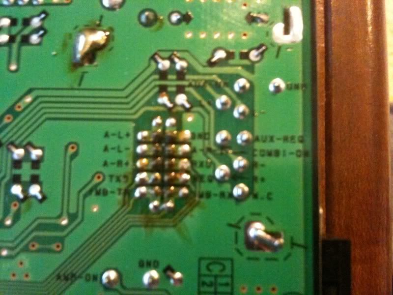
3. Solder the following wires. I determined where the L+, L-, R+, R- wires go by using a multimeter in conductivity mode and tracing the pins from the CD changer connector. The labels on the picture are from memory so please double check them with a multimeter. The pin out diagram for the CD changer connector was found here: http://carstereohelp.net/wireharness_Nissan2.htm.
Last edited by tillor; 07-29-2009 at 11:57 AM.
07-29-2009, 12:03 PM
#204
Junior Member
Join Date: Aug 2007
Location: Salem, OR
Posts: 26
Look here: http://ryft.org/index.php?title=1995...Bose_HU_AUX_in
Thats a more detailed write up I did. needs better pictures, but you should see what you need to do.
Could an admin edit the first post to include that link?
Thats a more detailed write up I did. needs better pictures, but you should see what you need to do.
Could an admin edit the first post to include that link?

 09-16-2009, 12:48 PM
#206
Senior Member

Join Date: Aug 2000
Posts: 2,529
anyone try this with a shield stereo headphone cable alone ? its got a ground shield and a l and R signal, all we would need to do is basically link up the L+ and R+ and then the common to the ground shield on both.
Also there are not many pics in the OP , does someone have the exact solder points on the PCB ?
Also there are not many pics in the OP , does someone have the exact solder points on the PCB ?
 10-28-2009, 06:49 PM
#208
Newbie - Just Registered

Join Date: Jun 2005
Location: houston tx
Posts: 1
looking for someone who can install this in my '02 i35 in Houston TX.
just need to plug my iphone into the car stereo. dont care how it works, just dont want to use FM transmitter anymore or tape deck adapter.
shoot me an email. Quick771@Gmail.com
thanks
Chris
just need to plug my iphone into the car stereo. dont care how it works, just dont want to use FM transmitter anymore or tape deck adapter.
shoot me an email. Quick771@Gmail.com
thanks
Chris
11-14-2009, 07:03 PM
#209
Junior Member
Join Date: Aug 2007
Location: Salem, OR
Posts: 26
So I've been messing around with this. I know that people have been looking for the diagram that shows which wires are which. Just for a short answer, in the second post there is a picture of wires soldered to the board, the 4 grouped together are L-, L+, R-, R+. As for the other 3, the furthest outside wires connected together will cause the AUX to show up on the display, so one must be ground and the other the aux. I have no idea what the third is. I have a bose unit from '96 and it worked this way.
 12-04-2009, 07:56 PM
#211

CLARION AUX Works: Maxima 97 non-Bose single CD (the cassette tape lid has a number CN585) Since it's not a Bose it must be a Clarion.
OK I got music from the Ipod. Here is how I wired it with 7 wires. These all come from the CD changer connector, that are not being used:
Radio Shack SWITCH I used
The switch I used is a single pole double throw (SPDT) with 3 leads.
AUX-ON soldered to switch (center lead)
RXD soldered to switch (outside lead)
GND soldered to the switch (outside lead)
LCH+ to Positive Left Channel (center pin on RCA connector)
LCH- to Negative Left Channel (outside lead on RCA connector)
RCH+ to Positive Right Channel (center pin on RCA connector)
RCH- to Negative Right Channel (outside lead on RCA connector)
Remember it's very quiet so turn it up to hear it. I have external amps on mine so it gets good volume.
Next, install the $29.00 ebay Harman Karmon Drive Play.
Sorry about waking this old thread.
Thx.
Last edited by rrg; 12-05-2009 at 04:38 PM.
12-06-2009, 03:42 PM
#212
Senior Member

Join Date: Nov 2009
Posts: 176
Best mod ever! just installed everything back together, works like a charm, Only thing i found odd was my ipod needed constant power from its 12v charger otherwise there is alot of digital static, but with it,Sounds amazing.
Damn bose knowes quailty, speakers sound awesome 13 years later
Damn bose knowes quailty, speakers sound awesome 13 years later
 12-25-2009, 06:31 PM
#214
Senior Member

Join Date: Sep 2007
Posts: 1,042
i read pages 1-3 noone seem to give a true answer if it worked for the 99 head unit.
i had a 96 head unit did the mod. WORKED SO GOOD. then the radio started going all postal on me so i got a 99 bose head unit from a path finder (looks the same as the 99 gle model).
so not only did i get this unit for free at my job, it plays better, everything works so prefect too.
i just need to know does this work off the 99 radio??


 i just use the tape deck with and adapter from an old discman

 02-14-2010, 06:16 AM
#219
Newbie - Just Registered

Join Date: Feb 2010
Posts: 1
Works great for ipod
I wanted to clear up some confusion that I and others have.
After reading through thread a couple of times I worked up the nerve to do this. BTW - it works great! Thank Dan.
In Dans original instructions there is a pic with 7 wires. He only explains 6 connections so what is with the extra wire. Much later in thread "rrg" posts:
Radio Shack SWITCH I used
The switch I used is a single pole double throw (SPDT) with 3 leads.
AUX-ON soldered to switch (center lead)
RXD soldered to switch (outside lead)
GND soldered to the switch (outside lead)
LCH+ to Positive Left Channel (center pin on RCA connector)
LCH- to Negative Left Channel (outside lead on RCA connector)
RCH+ to Positive Right Channel (center pin on RCA connector)
RCH- to Negative Right Channel (outside lead on RCA connector)
Thanks "RXD"
All this info is essential and explains the 7th wire going to RXD. I did not understand why the RXD would be necessary so I tried connecting the AUX On and Ground with single throw switch and two leads like Dan stated only and it did not work. I tried wiring the AUX ON and RXD together on the same pole on switch and there was a small "click" in stereo followed by "AUX" on display! It worked!
The only other info I would pass along concerns the soldering locations on the Dans wire pic 'cause I never was able to find that "pdf" file either. Moving from left to right the solder points are as follows:
Ground, AUX On, the 4 together are R+ on top of R-, the L+ on top of L- (not sure why L is right of the R's but I did not design the board..). The pin connection to the far right is a mystery to me. The RXD on my stereo is located directly right of AUX ON. I simply soldered the switch lead between the two solder pins to wire together.
As for sound...I read problems with volume and static when in pause on the ipod. I do not experience any of these problems. Any louder and the speakers would blow and no static. The sound quality is exceptional!
Overall I still cant believe I got this to work but very glad I got the nerve to try. It is not a big deal but you will need the multimeter and some practice soldering. I used an old network card from and old PC...
Good Luck!
03-31-2010, 01:17 PM
#220
Junior Member

Join Date: Sep 2007
Posts: 99
http://ryft.org/wiki/index.php?title...Bose_HU_AUX_in
Just stopped by to see what was going on, if anyone was wondering where my link went.. here it is. Sorry bout the change, my friend swapped things around...
Just stopped by to see what was going on, if anyone was wondering where my link went.. here it is. Sorry bout the change, my friend swapped things around...

 04-26-2010, 06:01 PM
#223
Newbie - Just Registered

Join Date: Oct 2007
Posts: 11
04-26-2010, 06:02 PM
#224
Newbie - Just Registered
Join Date: Oct 2007
Posts: 11
Check out the video I just put together... Enjoy!
anyone try this with a shield stereo headphone cable alone ? its got a ground shield and a l and R signal, all we would need to do is basically link up the L+ and R+ and then the common to the ground shield on both.
Also there are not many pics in the OP , does someone have the exact solder points on the PCB ?
Also there are not many pics in the OP , does someone have the exact solder points on the PCB ?
04-26-2010, 06:03 PM
#225
Newbie - Just Registered
Join Date: Oct 2007
Posts: 11
04-26-2010, 06:04 PM
#226
Newbie - Just Registered
Join Date: Oct 2007
Posts: 11
04-26-2010, 06:05 PM
#227
Newbie - Just Registered
Join Date: Oct 2007
Posts: 11
04-26-2010, 06:06 PM
#228
Newbie - Just Registered
Join Date: Oct 2007
Posts: 11
04-26-2010, 06:07 PM
#229
Newbie - Just Registered
Join Date: Oct 2007
Posts: 11
Check out the video I just put together... Enjoy!
Man, I guess I just want it all. Other then FM tranmitter or Tape Adapter. I have yet to see something that will let me keep my CD Changer. The AUX that I have only works when I put a Audio CD in the Navi. Am I missing something? Or with this mod work for me?
Sorry that is a bit confusing.
I have a '02 Max. with a Factory Navi. with a 6 Disc cd changer in the trunk. Like to keep the cd changer but add a Aux port for a MP3 player. I dont have a Sat. button is there a way to get this to work?
Sorry that is a bit confusing.
I have a '02 Max. with a Factory Navi. with a 6 Disc cd changer in the trunk. Like to keep the cd changer but add a Aux port for a MP3 player. I dont have a Sat. button is there a way to get this to work?
04-26-2010, 06:08 PM
#230
Newbie - Just Registered
Join Date: Oct 2007
Posts: 11
04-26-2010, 06:09 PM
#231
Newbie - Just Registered
Join Date: Oct 2007
Posts: 11
 04-26-2010, 06:12 PM
#232
Newbie - Just Registered
Join Date: Oct 2007
Posts: 11
Check out the video I just put together... Enjoy!
I tore apart my 2K2's Bose HU and could not get to the circuit board. I removed 2200 screws and still could not get the CD changer separated from the HU, in order to get a clean look at the solder connections.
I buttoned it back up and thought I might try intercepting the tape deck leads at the white multi-pin connector as it goes IN to the HU. Problem #1, you can't select TAPE as an input unless there's a tape IN THE DECK. That option is out. Problem #2, I thought I could piggy-back into the CD player leads, and maybe by leaving at least 1 blank CD in the changer, that would work. Still not sure if that plan will bear any fruit - I disconnected the 10-pin white connector and all 10 wires are now loose and no longer in their correct arrangement. Can anyone here tell me how to arrange these wires again? Red, Yellow, White, Green, Green & White, Purple, Red & White, Black, Gray, Red& Yellow.
Here's a pic of the black connector that I need to feed these colors into. Thanks in advance for any help.
http://picasaweb.google.com/mauryrut...08545381787778
Maury
 05-31-2010, 10:46 PM
#234
Junior Member

Join Date: May 2010
Location: San Diego, CA
Posts: 18
WTF!?
I just finished putting everything back together and it works great. Except now when I turn my parking lights/headlights on the aux turns off.
I did the always illuminated clock mod too. Does this have anything to do with it?
I did the always illuminated clock mod too. Does this have anything to do with it?
 06-01-2010, 08:38 PM
#236
Senior Member

Join Date: Dec 2009
Posts: 469
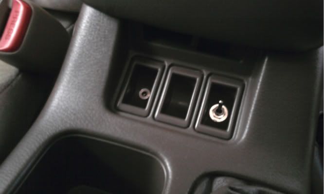
The switch and port are wicked! Very slick install.
I kind of want to try and wire a nice over-the-speakers setup into my Max now, sort of like the Youtube video a few posts up, which is the answer to every post about the 2k2 install. I'm trying to figure out how I'd manage. I have a Nokia which came with a little remote control with play, pause, reverse/forward, and answer/hang up buttons on it. I figure it should be possible to wire the audio parts of this into my Bose HU and the microphone into a mic I've placed somewhere in the car where it can pick up my voice.
I don't know what sort of mic I'd use to pick up my voice nicely from a bit of a distance. I also don't know where I'd put it - I don't want to cut any holes in the plastics, but I'm thinking a little bug hanging from the top of the A-pillar trim could work; that's where it was on my dad's old Lincoln Continental. For an easier install, a shorter wire, and potentially better voice pickup, the top of the steering column might work nicely.
The rest shouldn't be difficult. The Nokia remote outputs to the standard four-wire output: mic, two audio, and ground. It would probably be simple to split the mic wire out of a four-wire cable so it can go somewhere separate fro the audio. That wire would then plug into the unmodified Nokia remote and then into the phone. I'd plug in the phone, start the music, drop it wherever I liked, and from then onwards control everything with the remote, which I could Velcro or mount nicely somewhere inconspicuous and easily at hand.
Doubt I'll ever do it but it would be cool. Maybe I'll look into it next weekend.
EDIT: Wau...my phone came with one of these cables: http://cgi.ebay.com/Nokia-3-5mm-CA-7...item2a06f1aec6 Nokia CA-75U
It's a beautiful cable, really nice rubber, but I think it would be perfect for this. The cable is split from the input into three RCA plugs, so I wouldn't need to do any splicing - just chop off the heads of the two audio cables and solder them as appropriate, then connect the third to a mic wherever I want. I even have some RCA extension cable lying around the house.
But damn it, it's such a nice cable...well, a new one is $3 on eBay and I've never used it in the two years I've had the phone...but it even smells nice, it seems such a shame to chop it up...
Last edited by j-dawg; 06-01-2010 at 09:26 PM.
06-04-2010, 09:00 PM
#237
Senior Member
Join Date: Dec 2009
Posts: 469
I did it.
The idea was to use the AV (yellow-white-red) cable that came with my phone as stereo audio and a microphone. These would plug into the Nokia AD-54 remote control that came with my phone. I went to Fry's and bought all the components I'd need: a microphone, some couplers, and some wire.
The basic idea of the setup can be described as below:

This image (and all the others, 'cause I totally forgot it until the end) neglect the remote control that was really the main reason I made this setup. it's a little plastic box with some buttons on it, a wire to plug into the phone, and a headphone port:

It's the box on the left. This allows me to play/pause/stop/fast forward/reverse music and pick up/hang up calls, all pretty much without having to look away from the road.
My soldering is terrible so I managed to break a thousand joints during the process of installation. In fact, that was the single biggest holdup for this whole project. As you can see, I broke the connection for the right+ channel, so I followed the trace and soldered the wire directly to the surface-mount resistor at the end of its trace.

My soldering is so bad that I think some of it has already come undone: I noticed late yesterday a distinct lack of bass in my music that wasn't there in the morning. I'm planning to redo the joints with stranded wire some time soon, or just buy the $2 d-sub kit mentioned elsewhere in this thread, the crimp connectors from which I can connect to the changer port.

This was the basic idea for the mic. I wanted it mounted in the little blank panel on the dash next to the dimmer switch, where it could be pointed straight at me, since I had little faith in the $4 microphone I had bought. As you can see, I have subjected it to coupler hell and I was worried that the sound might not come through all right. I wanted to avoid soldering the mic cable because it would be subjected to a lot of jostling during the installation.

The cables run through here. I took this photo before deciding to run the switch through here as well.

The setup with the electrical work finished. It took a remarkably short time to get to this point - of course, I hadn't yet broken every solder joint twice, so I was excited about how quickly the mod was progressing.

I didn't have a drill bit exactly the right size as the microphone, but I did notice that my key was exactly as wide at the shank as the part of the microphone that I wanted to grab. So I drilled a 5/16" hole and reamed it out with my key.

It's a perfect press-fit. Tight enough that no amount of jiggling will move it, but just enough room to twist the mic if necessary. The switch I bought was listed on the manufacturer's website as needing a .25" hole, which was easy enough. In the process of drilling these holes, I managed to skin my finger and slightly break the panel I drilled them in. No biggie, though - it still sticks in place.

Dash bezel back in place. I wanted the mic and switch to be to the left of the dimmer control, but the couplers were stiff and wouldn't fit, so I had to move it inside.

The finished product. I forgot to take a picture of the remote, but you can see the cable poking out from the upper AC vents. This terminates in a 3.5mm plug (seen here) which is holding up the remote; the wire out from the remote then goes to a TRRS connector which plugs into the phone. This plug runs through a hole I drilled in the little tray below the radio and out of its door, so it can be tucked in when not in use. The phone sits in the ashtray. The only visible elements of the mod are the mic and switch on the panel and the remote chillin' next to the radio.
I wasn't too sure about the mic, but people say they can hear me clearly at highway speeds, so it seems to have been up to the job for less than $5, and that was the most expensive thing I bought. So I've got a good handsfree setup for under $15 in parts.
It also works for regular MP3 players and what-have-you with a 3.5mm jack, since in those applications the mic wire is just shorted to ground. It should work for regular phones using TRRS connectors as headset plugs too. Interesting note: because Apple is wack, they reversed the ground and microphone rings on the TRRS connector so that only iPhone-specific headsets work with iPhones and so that iPhone headsets work only with iPhones. Thus, my car's setup will work with any TRRS headset phone except the iPhone.
Last edited by j-dawg; 06-04-2010 at 09:07 PM.
06-07-2010, 05:13 PM
#238
Newbie - Just Registered

Join Date: May 2010
Posts: 9
I have an 02 with the factory nav unit. I have the tape deck part out, but I am confused as to where I need to solder. Mine looks a little bit different than the one above and I'm not sure how much of that is used for your mic and how much is for the aux input. Since my board looks a little different, it's hard to tell where you soldered to. I am creating a silent CD to play while using this and I actually got the idea from this link: http://www.instructables.com/id/Add-...-your-cars-st/. I got this part from radio shack (http://www.radioshack.com/product/in...ductId=2103451) and I am trying to solder the connections and mount it somewhere. Can someone please tell me where to solder?
06-07-2010, 05:46 PM
#239
Newbie - Just Registered
Join Date: May 2010
Posts: 9
So here are some pictures of what I'm working with.
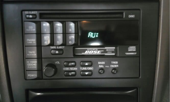
Here is what my unit looks like:
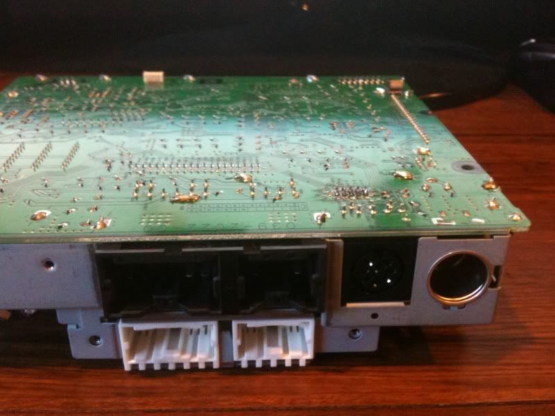
Here is a closeup of the board right next to the CD changer port (sorry it is a little fuzzy because I took it using my phone, but you can read the labels):
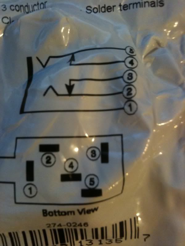
And finally, a picture of the diagram on the back of the aux input jack I am trying to install on the board:
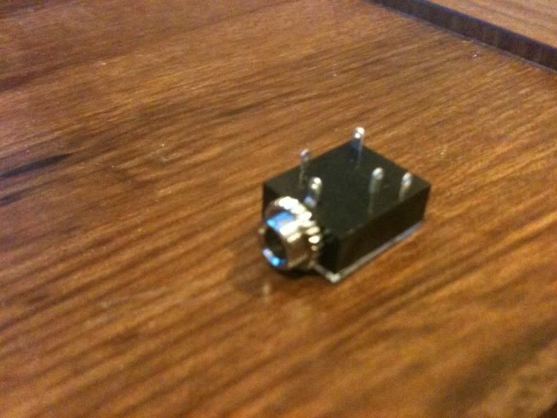
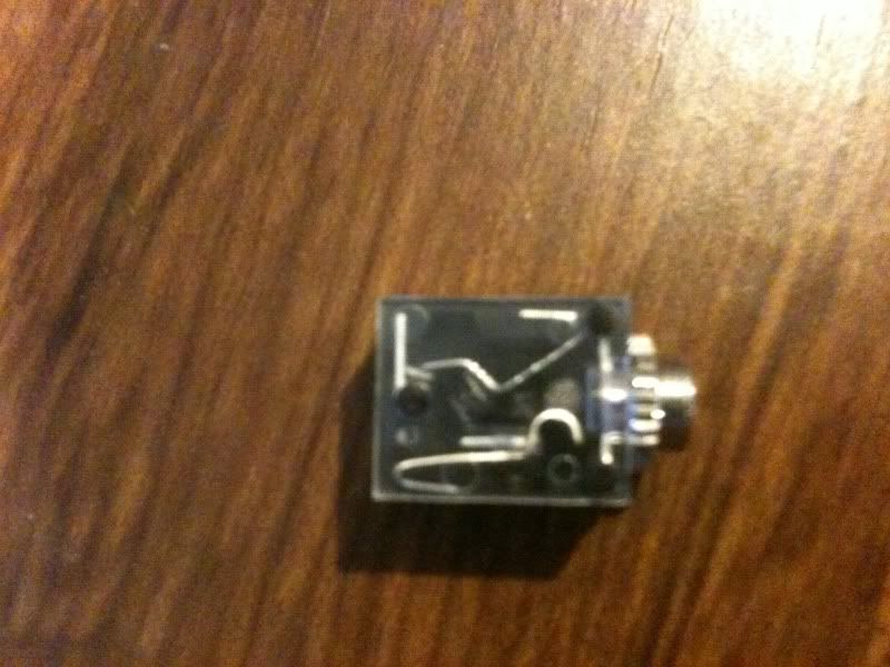
I am using 18/2 stranded wire and I am ready to solder, but I haven't messed with circuitry before and want to make sure I don't do anything stupid. I am not really sure how to mount this aux jack really. Here is what it looks like:
I'm not really sure how to connect this. Anyone care to help a little? Any advice helps. Thanks!
Here is what my unit looks like:
Here is a closeup of the board right next to the CD changer port (sorry it is a little fuzzy because I took it using my phone, but you can read the labels):
And finally, a picture of the diagram on the back of the aux input jack I am trying to install on the board:
I am using 18/2 stranded wire and I am ready to solder, but I haven't messed with circuitry before and want to make sure I don't do anything stupid. I am not really sure how to mount this aux jack really. Here is what it looks like:
I'm not really sure how to connect this. Anyone care to help a little? Any advice helps. Thanks!
06-07-2010, 07:15 PM
#240
Newbie - Just Registered
Join Date: May 2010
Posts: 9
So I found all the 7 terminals but I'm not sure what to do with the other ends of the wires lol. I know I'm a retard, but can someone please explain what to do with the other ends and how they will connect to my 1/8" jack pictured above??

