VAFC-II setup template
 03-12-2006, 09:36 PM
#1


VAFC-II setup template
It has come to my attention that some people could use a little extra help when setting up the VAFC-II for the Maxima. Many are following my recommendations for getting it over the SAFC-II, which I find encouraging, but I suppose I need to clarify more of the details.
The reasoning for getting the V over the S really has nothing to do with it's 'vtec control' or in our case 'rpm switch'. That part isn't a direct wire setup anyway. And it certainly would have nothing to do with attempting to control the VTCs on the VQ35, as some mistakenly suspect.
It's really all about the NE points for setting up the fuel corrections. The SAFC-II has a twelve point by two point map (12x2) which means you can setup 12 rpm points throughout the rev range and 2 throttle points for correction. Anything in between your specified RPM and throttle points is interpolated . The SAFC-II can also be manually switched to a second data file or map to be used with Nitrous or some other more or less aggressive tuning parameters you might need.
The VAFC-II essentially uses both of these 12x2 maps together, effectively making it a 24x2. But it has to be triggered to select between these two maps by a Hvt and Lvt setting (12x2 high vtec, 12x2 low vtec).
Now for the example setups:
So for most of these cars that can only rev to 6500 or 6600, we would set the Lvt to Hvt setting at 4200rpm and the Hvt to Lvt at 4100 (for some reason it wont let you make them the same). Doing this means that the VAFC-II will switch over from one 12 point map to the other 12 point map at 4200rpm. Now you'll need to setup the Lvt NE (RPM) points, obviously you'll want to end the Lvt points at or before 4200rpm because that is where you just set the crossover. If you set Lvt points past your crossover point they just go to waste and you won't make use of the full 24. A good selection would look something like this:
Lvt 1200,1600,2000,2400,2600,2800,3000,3200,3400,3600, 3800,4000
Hvt 4200,4400,4600,4800,5000,5200,5400,5600,5800,6000, 6200,6400
If you have some A/F problems at the crossover point you may need to adjust those settings. I don't think the VAFC-II will interpolate between the Hvt and Lvt maps.
Notice I have listed settings as low as 1200rpm, this isn't really usefull to everyone but those with larger MAF sensors or larger injectors can make use of the low rpm/low throttle settings to keep the ECU fuel trims in check (they really need to be as close to zero as possible).
As for the wiring setup, keep in mind that the VAFC-II only has settings for MAP sensors, but it still needs to be wired to your vehicles MAF sensor. And for display purposes I generally use the setting of +15psi, which does not give by any means an accurate display of air mass flow or MAF voltage, it does somewhat put the MAF output into some discernible perspective. It's also cool to show off to your friends, and those who think you have forced induction anyway.
I realize there is still much left out here but I'll try to answer the questions as they arise. I don't have a VAFC-II to look at, so I am having to do this from memory.

 03-12-2006, 09:46 PM
#4
Originally Posted by steven88
Just letting you know...I'm running the following INITIAL SETUP settings
1 in & 1 out, 6 cylinder, up right arrow, vtec type 1
no problems so far...anybody else running diff settings?
1 in & 1 out, 6 cylinder, up right arrow, vtec type 1
no problems so far...anybody else running diff settings?
03-12-2006, 09:52 PM
#5
I really don't know...well I know the up-right arrow means something about the TPS voltage...u can test it out manually to see where your at...but from what I know, all maximas have this same voltage...so u pick the up right arrow...
dunno too much about the 1 in and 1 out....and vtec type
dunno too much about the 1 in and 1 out....and vtec type
03-12-2006, 11:13 PM
#6

want to wire either a vafc or safc to the sunglass holder...will the wiring for a vafcII reach there? i know they safcII is about 7 feet long...how long do you think the wiring is for the vafc..you think the wiring can be easily made longer
03-12-2006, 11:19 PM
#7
when I measured my VAFCII....it barely reaches the sunglass holder...but I didn't completely stretch out the wires...I'm sure it would reach if you tried hard enough....
others say it won't reach...but this is from MY personal experience with MY VAFCII....take your pick
others say it won't reach...but this is from MY personal experience with MY VAFCII....take your pick
 03-15-2006, 07:59 AM
#14
I have Haydn's manual still if you wanna look at it for more info Matt, or you can play around with mine for the other functions and features.
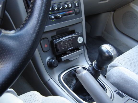
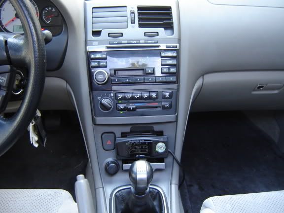
Here's where mine is mounted. Perfect, and I can still see the clock.

Here's where mine is mounted. Perfect, and I can still see the clock.
03-15-2006, 06:48 PM
#15

The in & out settings have to match & that's as much as I know about those. Have mine set at 4. On the VAFCII the vtec type should be set at med to use it as an RPM switch for the VIS. The VAFC will not actuate the VIS, known from personal headaches & wasted $... VAFCII on the way
Nice write up, where were you last year about this time
Here's where I mounted mine

Nice write up, where were you last year about this time
Here's where I mounted mine
 03-19-2006, 06:19 PM
#18
Originally Posted by NashCar
So I'm a little confused. Maybe I just missed it somewhere. How exactly does this work with a MAF sensor if its made for a MAP sensor?? Like, how does it measure how much air is comming in?
It knows nothing about air. All it sees is an input voltage which it translates to a different voltage based on your settings per thottle (voltage) and RPM (frequency).
03-24-2006, 01:42 PM
#19
Got mine finally installed and set it up as per the info in this thread 

My install thoughts/comments are here:
http://forums.maxima.org/showthread.php?t=463709
My install thoughts/comments are here:
http://forums.maxima.org/showthread.php?t=463709
03-24-2006, 02:11 PM
#20
Originally Posted by Puppetmaster
Got mine finally installed and set it up as per the info in this thread
[IMG]http://i11.photobucket.com/albums/a190/Puppetmaster1/VAFCII/DSCN4427.jpg[IMG]
[IMG]http://i11.photobucket.com/albums/a190/Puppetmaster1/VAFCII/DSCN4427.jpg[IMG]
 03-27-2006, 05:04 PM
#23
Here is the wiring template I started working on.
http://vq35de.com:2002/A33x_ECM.pdf
Look it over and offer suggestions or requests.
http://vq35de.com:2002/A33x_ECM.pdf
Look it over and offer suggestions or requests.

 05-22-2006, 10:04 PM
#28
Originally Posted by aznsap
i thought that open loop didn't come into effect until 3000 rpm? does that mean we can start the Lvt @ 3000 rpm and go up to redline in smaller increments?
if you have simple bolt ons, starting at 3k would be just fine as well

