
CXJ PERFORMANCE 2pc 7th Gen Thermal Phenolic Spacers Install How-To
 11-08-2011, 07:33 PM
#1
Senior Member
Thread Starter

Join Date: Nov 2010
Location: Maryland
Posts: 4,020
CXJ PERFORMANCE 2pc 7th Gen Thermal Phenolic Spacers Install How-To
DISCLAIMER : I AM BY NO MEANS RESPONSIBLE FOR ANY DAMAGE YOU DO TO YOURSELF OR YOUR CAR IN THE PROCESS OF THIS INSTALLATION. BY READING THIS AND PROCEEDING WITH THE INSTALL YOU ARE ACCEPTING ALL LIABILITY FOR THE WORK YOU PERFORM ON YOUR CAR. IF YOU ARE NOT COMFORTABLE DOING THE INSTALL AFTER READING THIS, PLEASE CONTACT A PROFESSIONAL SHOP TO HAVE YOUR SPACERS INSTALLED.
CXJ PERFORMANCE 2pc 7th Gen Thermal Phenolic Spacers Install How-To
…and Throttle Body Bypass
This is an install thread explaining how to install the CXJ PERFORMANCE 2pc 7th Generation Maxima Thermal Phenolic Spacers as well as how to do a Throttle Body Bypass. First I’d like to thank you Cory for making a quality product for the newer Maximas. I think everyone agrees that there aren’t enough aftermarket modifications available for this generation so kudos to you for paving the way with the first 7th Generation Maxima Thermal Phenolic Spacer kit.
Tools required:
10mm socket wrench, 13mm socket wrench, multi-size Allen wrench, flathead screwdriver, pliers, RTV gasket maker, CXJ PERFORMANCE 2pc Thermal Phenolic Spacer kit w/ included hardware (4 extended throttle body bolts with lock washers, 4 extended intake manifold bolts with lock washers, 2 extended intake manifold studs, hose mender + hose caps), 50/50 Antifreeze coolant mixture, several large rags
A few warnings before proceeding:
Don't work on a hot car; obviously the engine is hot as well as the coolant which can scald you if you don't let it cool.
With your intake or throttle body off, NEVER touch the valve inside. If you move this even slightly you could damage the throttle body or at least require an idle-relearn procedure which you may need to pay Nissan to fix for you.
After removing the intake manifold, IMMEDIATELY plug up the holes on the engine block with rags to prevent dropping anything in there. If you drop anything in there your engine is finito.
Removing The Manifold And Installing The Spacers
Step 1 - Remove your 3 primary engine covers; this requires an Allen wrench and taking off some plastic fasteners. If you get stuck on this step I would highly advise doing more research before attempting this how-to
Step 2 - Remove your intake; you just need the piece that attaches to the throttle body removed so you have access to that area

Step 3 - Remove your aftermarket strut bar (if you have one); simply unbolt the strut bar from the mounts and leave the mounts on the car it is easy to put back on

Step 4 - Disconnect the metal tube assembly (fuel and vacuum lines) from the top/front of the manifold by removing the 5 10mm bolts holding on the top section

Step 5 - Remove the 2 10mm bolts on the front of the manifold holding the metal tube assembly onto the manifold

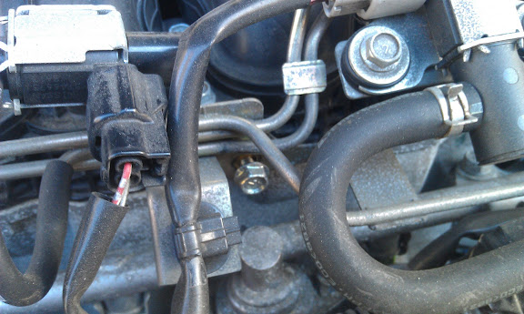
Step 6 - Remove this small hose from the metal tube that snakes around on the right side of the manifold; using a small flathead screwdriver can help you work it off

Step 7 - (Throttle Body Bypass) On the lower left side of the throttle body there are two coolant hoses connected; using a pliers you can squeeze the metal tabs of the ring holding it on and work it backwards. Pull the hoses off then one at a time and be mindful coolant will leak out. You can use a vice grips to clamp the hose while removing the other hose if you want, or just work quickly and remove the other hose.
Instead of using the supplied hose mender to join the two coolant lines, simply remove the shorter hose (the 2 coolant hoses are different lengths) and plug the longer hose onto the spot you removed the short hose from. (great tip from copekyle - thanks!). If you still want to use the supplied hose mender, do your best to maneuver the hoses so there are no hard 90 degree angles.
Note: This step will make a mess and you may need to add more coolant depending on how much you leak.

Step 8 – (Throttle Body Bypass) Put hose caps on the two connections you removed the hoses from on the throttle body
Note: If you want you can skip the throttle body bypass but will still need to remove these hoses to get the manifold off the car. I recommend using plugs or vice grips to clamp them shut while not attached to anything.
Step 9 - Detach this wire harness from its metal clip on the lower right corner of the throttle body; unplug the connection on the right as well by squeezing it and pulling back on the wire harness

Step 10 - Remove the hose from this metal tube on the right side of the manifold that is in the center of this picture

CXJ PERFORMANCE 2pc 7th Gen Thermal Phenolic Spacers Install How-To
…and Throttle Body Bypass
This is an install thread explaining how to install the CXJ PERFORMANCE 2pc 7th Generation Maxima Thermal Phenolic Spacers as well as how to do a Throttle Body Bypass. First I’d like to thank you Cory for making a quality product for the newer Maximas. I think everyone agrees that there aren’t enough aftermarket modifications available for this generation so kudos to you for paving the way with the first 7th Generation Maxima Thermal Phenolic Spacer kit.
Tools required:
10mm socket wrench, 13mm socket wrench, multi-size Allen wrench, flathead screwdriver, pliers, RTV gasket maker, CXJ PERFORMANCE 2pc Thermal Phenolic Spacer kit w/ included hardware (4 extended throttle body bolts with lock washers, 4 extended intake manifold bolts with lock washers, 2 extended intake manifold studs, hose mender + hose caps), 50/50 Antifreeze coolant mixture, several large rags
A few warnings before proceeding:
Don't work on a hot car; obviously the engine is hot as well as the coolant which can scald you if you don't let it cool.
With your intake or throttle body off, NEVER touch the valve inside. If you move this even slightly you could damage the throttle body or at least require an idle-relearn procedure which you may need to pay Nissan to fix for you.
After removing the intake manifold, IMMEDIATELY plug up the holes on the engine block with rags to prevent dropping anything in there. If you drop anything in there your engine is finito.
Removing The Manifold And Installing The Spacers
Step 1 - Remove your 3 primary engine covers; this requires an Allen wrench and taking off some plastic fasteners. If you get stuck on this step I would highly advise doing more research before attempting this how-to
Step 2 - Remove your intake; you just need the piece that attaches to the throttle body removed so you have access to that area
Step 3 - Remove your aftermarket strut bar (if you have one); simply unbolt the strut bar from the mounts and leave the mounts on the car it is easy to put back on
Step 4 - Disconnect the metal tube assembly (fuel and vacuum lines) from the top/front of the manifold by removing the 5 10mm bolts holding on the top section
Step 5 - Remove the 2 10mm bolts on the front of the manifold holding the metal tube assembly onto the manifold
Step 6 - Remove this small hose from the metal tube that snakes around on the right side of the manifold; using a small flathead screwdriver can help you work it off
Step 7 - (Throttle Body Bypass) On the lower left side of the throttle body there are two coolant hoses connected; using a pliers you can squeeze the metal tabs of the ring holding it on and work it backwards. Pull the hoses off then one at a time and be mindful coolant will leak out. You can use a vice grips to clamp the hose while removing the other hose if you want, or just work quickly and remove the other hose.
Instead of using the supplied hose mender to join the two coolant lines, simply remove the shorter hose (the 2 coolant hoses are different lengths) and plug the longer hose onto the spot you removed the short hose from. (great tip from copekyle - thanks!). If you still want to use the supplied hose mender, do your best to maneuver the hoses so there are no hard 90 degree angles.
Note: This step will make a mess and you may need to add more coolant depending on how much you leak.
Step 8 – (Throttle Body Bypass) Put hose caps on the two connections you removed the hoses from on the throttle body
Note: If you want you can skip the throttle body bypass but will still need to remove these hoses to get the manifold off the car. I recommend using plugs or vice grips to clamp them shut while not attached to anything.
Step 9 - Detach this wire harness from its metal clip on the lower right corner of the throttle body; unplug the connection on the right as well by squeezing it and pulling back on the wire harness
Step 10 - Remove the hose from this metal tube on the right side of the manifold that is in the center of this picture
Last edited by Ghozt; 01-03-2012 at 07:50 PM.
 11-08-2011, 07:33 PM
#2
Senior Member
Thread Starter
Join Date: Nov 2010
Location: Maryland
Posts: 4,020
Step 11 - Unlatch the plastic holder next to the hose you just disconnected and lift it out of the plastic holder
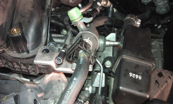
Step 12 - Remove the 4 10mm bolts surrounding the letter "C" on your Manifold.

Step 13 - Remove the 2 nuts from the intake manifold studs


Step 14 - On the left rear side of the manifold there are two black hoses attached. They are difficult to get to but you'll need to get back there with pliers and squeeze the metal clamps holding them on, wiggle the clamps backwards a couple inches, and then disconnect the hoses from these two connections here. Again, a small flathead screwdriver can help you get these hoses off

Step 15 – On the rear of the manifold close to where the hoses from the previous step connected, there is a 13mm bolt, feel around for it going in on the left side of the manifold. It is a little hard to get back there but you can get the bolt loose enough to take it the rest of the way out with your hand.

Step 16 - Pull the metal tube assembly away from the manifold, it pulls forward for the most part but might spring back. It will need to be out of the way when you pull the manifold off in the next step

Step 17 - You should now be able to lift off the intake manifold straight upwards (keeping mindful of the studs used to guide it on both left and right sides) then it pulls forward towards you

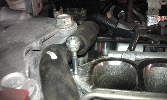
STOP! NEXT STEP IS CRITICAL!
Step 18 - You want to immediately stuff large rags into these openings so you don't drop anything down into them. If you do your engine is done. Do not use small rags that fall into the hole. An alternative to rags is to tape over the holes with masking tape which was a great suggestion by ampire.


Step 19 – (Throttle Body Spacer) Remove the throttle body by taking out the 4 allen-head bolts holding it on. DO NOT TOUCH THE VALVE.

Step 20 - (Throttle Body Spacer) Install the throttle body spacer using an RTV gasket on one side (notice there are plastic gaskets on the manifold itself). Apply a thin nickel-thick layer of RTV gasket maker to the side of the spacer that will apply to the throttle body, and push it on tight. If excess squeezes out that is a good sign of a seal; but be careful of cleaning up the excess from the inside! DO NOT TOUCH THE VALVE.

Step 12 - Remove the 4 10mm bolts surrounding the letter "C" on your Manifold.
Step 13 - Remove the 2 nuts from the intake manifold studs
Step 14 - On the left rear side of the manifold there are two black hoses attached. They are difficult to get to but you'll need to get back there with pliers and squeeze the metal clamps holding them on, wiggle the clamps backwards a couple inches, and then disconnect the hoses from these two connections here. Again, a small flathead screwdriver can help you get these hoses off
Step 15 – On the rear of the manifold close to where the hoses from the previous step connected, there is a 13mm bolt, feel around for it going in on the left side of the manifold. It is a little hard to get back there but you can get the bolt loose enough to take it the rest of the way out with your hand.
Step 16 - Pull the metal tube assembly away from the manifold, it pulls forward for the most part but might spring back. It will need to be out of the way when you pull the manifold off in the next step
Step 17 - You should now be able to lift off the intake manifold straight upwards (keeping mindful of the studs used to guide it on both left and right sides) then it pulls forward towards you
STOP! NEXT STEP IS CRITICAL!
Step 18 - You want to immediately stuff large rags into these openings so you don't drop anything down into them. If you do your engine is done. Do not use small rags that fall into the hole. An alternative to rags is to tape over the holes with masking tape which was a great suggestion by ampire.
Step 19 – (Throttle Body Spacer) Remove the throttle body by taking out the 4 allen-head bolts holding it on. DO NOT TOUCH THE VALVE.
Step 20 - (Throttle Body Spacer) Install the throttle body spacer using an RTV gasket on one side (notice there are plastic gaskets on the manifold itself). Apply a thin nickel-thick layer of RTV gasket maker to the side of the spacer that will apply to the throttle body, and push it on tight. If excess squeezes out that is a good sign of a seal; but be careful of cleaning up the excess from the inside! DO NOT TOUCH THE VALVE.
Last edited by Ghozt; 11-14-2011 at 08:50 PM.
11-08-2011, 07:33 PM
#3
Senior Member
Thread Starter
Join Date: Nov 2010
Location: Maryland
Posts: 4,020
Step 21 - (Throttle Body Spacer) Re-install the throttle body onto the manifold using the new extended allen-head bolts and lock washers.

Step 22 – Remove the OEM intake manifold studs. The method I used was using the 2 OEM nuts that came off the studs – thanks for the idea Cory. If you screw two nuts onto the stud directly next to each other, you can use a wrench to rotate the lower one and it will turn the stud after it tightens up next to the other nut.
Step 23 - Install the new extended intake manifold studs by hand-tightening them. Now use the same 2-nut process but instead tighten the top nut to tighten the new studs in there nicely

Step 24 – (Intake Manifold Spacer) Install the intake manifold spacer directly onto the engine block using RTV sealant using the intake manifold studs to guide it into place. Do a quick test fit of the spacer to determine which side of the spacer touches the engine block - that is the side you need RTV on. Wipe down both the side of the spacer and the engine block with a rag to clean any dirt/oil from the surface. Apply a thin nickel-thick layer of RTV gasket maker to just the side that will touch the block, I used a disposable rubber glove and used my finger to smooth it out like peanut butter and smoothing it all out and taking off excess RTV. Remember we just want a thin vacuum seal layer so it doesn't need to be thick. Install it onto the engine block and clean up any excess that squeezes out on both inside/outside carefully using a paper towel or finger. BE EXTREMELY CAREFUL NOT TO DROP ANYTHING IN THESE HOLES WHILE WORKING.

Putting It All Back Together
Step 1 - Re-install the intake manifold by sliding the rear of it into the rear engine cavity, then slowly lowering the front down onto the new extended intake manifold studs to guide it perfectly into place.

Step 2 - Re-attach all the hoses you disconnected from the manifold (the 2 large hoses from the left/rear, the small hose on top, and the medium hose on the front/right side of the manifold) and use pliers to position the metal clamps near the ends of the hoses to hold them on.
Step 3 - Insert the hose on the right side of the manifold back into the black plastic holder you removed it from previously, close the plastic holder to secure the hose again
Step 4 - Re-install the original 2 10mm nuts on the new intake manifold studs on both left and right sides of the manifold and torque these to 8 ft/lbs (specs from Nissan so as not to warp the plastic manifold).
Step 5 - Install the new extended 4 10mm bolts using lock washers into the top of the manifold surrounding the "C" and torque them to 8 ft/lbs.

Step 6 - Re-attach the small 10mm bolts used to hold the metal tube assembly to the manifold (2 on the front of the manifold, and 5 on the top) and torque these to 8 ft/lbs.
Step 22 – Remove the OEM intake manifold studs. The method I used was using the 2 OEM nuts that came off the studs – thanks for the idea Cory. If you screw two nuts onto the stud directly next to each other, you can use a wrench to rotate the lower one and it will turn the stud after it tightens up next to the other nut.
Step 23 - Install the new extended intake manifold studs by hand-tightening them. Now use the same 2-nut process but instead tighten the top nut to tighten the new studs in there nicely
Step 24 – (Intake Manifold Spacer) Install the intake manifold spacer directly onto the engine block using RTV sealant using the intake manifold studs to guide it into place. Do a quick test fit of the spacer to determine which side of the spacer touches the engine block - that is the side you need RTV on. Wipe down both the side of the spacer and the engine block with a rag to clean any dirt/oil from the surface. Apply a thin nickel-thick layer of RTV gasket maker to just the side that will touch the block, I used a disposable rubber glove and used my finger to smooth it out like peanut butter and smoothing it all out and taking off excess RTV. Remember we just want a thin vacuum seal layer so it doesn't need to be thick. Install it onto the engine block and clean up any excess that squeezes out on both inside/outside carefully using a paper towel or finger. BE EXTREMELY CAREFUL NOT TO DROP ANYTHING IN THESE HOLES WHILE WORKING.
Putting It All Back Together
Step 1 - Re-install the intake manifold by sliding the rear of it into the rear engine cavity, then slowly lowering the front down onto the new extended intake manifold studs to guide it perfectly into place.
Step 2 - Re-attach all the hoses you disconnected from the manifold (the 2 large hoses from the left/rear, the small hose on top, and the medium hose on the front/right side of the manifold) and use pliers to position the metal clamps near the ends of the hoses to hold them on.
Step 3 - Insert the hose on the right side of the manifold back into the black plastic holder you removed it from previously, close the plastic holder to secure the hose again
Step 4 - Re-install the original 2 10mm nuts on the new intake manifold studs on both left and right sides of the manifold and torque these to 8 ft/lbs (specs from Nissan so as not to warp the plastic manifold).
Step 5 - Install the new extended 4 10mm bolts using lock washers into the top of the manifold surrounding the "C" and torque them to 8 ft/lbs.
Step 6 - Re-attach the small 10mm bolts used to hold the metal tube assembly to the manifold (2 on the front of the manifold, and 5 on the top) and torque these to 8 ft/lbs.
Last edited by Ghozt; 11-18-2011 at 05:35 PM.
11-08-2011, 07:34 PM
#4
Senior Member
Thread Starter
Join Date: Nov 2010
Location: Maryland
Posts: 4,020
Step 7 - Re-install the 13mm bolt on the rear of the manifold, you may have to position the plate the bolt goes through as it is just attached to a hose.
Step 8 – Plug the connection back in on the right side of the throttle body, insert the plastic piece from the wire harness back into the metal it was mounted on before. DO NOT TOUCH THE VALVE.
Step 9 – If you skipped the throttle body bypass, reconnect the two black hoses to the two metal tubes on the throttle body. Clamp them on with their metal clamps.
Step 10 - Re-install your intake
Step 11 – Re-install your engine covers
Step 12 – Top off your coolant with the 50/50 Antifreeze mixture
Step 13 – Reset your ECU / perform idle re-learn if necessary
Step 14 - Re-install your aftermarket strut bar if you have one. Depending on which brand you have you may experience clearance issues with the manifold. Washers, or spacers, can be used on the strut bolts to raise the strut bar up if you need a little more clearance.
Wait at least ONE HOUR for the RTV to set before turning on the engine or driving anywhere.
Enjoy your new CXJ PERFORMANCE Thermal Phenolic Spacers.
Update 11/16/11
Dyno runs:
Quick background - when we went to dyno the CVT as most of you know it produced wildly inaccurate results because you can't lock the car in at a specific gear. We did however find a way to generate consistent repeatable results with the CVT on the dyno; starting from a 10 MPH roll and revving to redline then letting off the pedal. The only downside is I have no idea how much max WHP my car puts out, but we can at least see the gains from the intake spacers being installed. We did 13 dyno pulls using DYNOJET and found that the CXJ IM and TB spacers showed gains of 10 HP & 9 Ft/Lbs of Torque @ 5543 RPMs.
7th Gen on the Dyno -

Dyno Chart

(the lighter colors are torque, the darker colors are HP)
Video of dyno pulls
http://www.youtube.com/watch?v=DbEli-7IkTs

Step 8 – Plug the connection back in on the right side of the throttle body, insert the plastic piece from the wire harness back into the metal it was mounted on before. DO NOT TOUCH THE VALVE.
Step 9 – If you skipped the throttle body bypass, reconnect the two black hoses to the two metal tubes on the throttle body. Clamp them on with their metal clamps.
Step 10 - Re-install your intake
Step 11 – Re-install your engine covers
Step 12 – Top off your coolant with the 50/50 Antifreeze mixture
Step 13 – Reset your ECU / perform idle re-learn if necessary
Step 14 - Re-install your aftermarket strut bar if you have one. Depending on which brand you have you may experience clearance issues with the manifold. Washers, or spacers, can be used on the strut bolts to raise the strut bar up if you need a little more clearance.
Wait at least ONE HOUR for the RTV to set before turning on the engine or driving anywhere.
Enjoy your new CXJ PERFORMANCE Thermal Phenolic Spacers.
Update 11/16/11
Dyno runs:
Quick background - when we went to dyno the CVT as most of you know it produced wildly inaccurate results because you can't lock the car in at a specific gear. We did however find a way to generate consistent repeatable results with the CVT on the dyno; starting from a 10 MPH roll and revving to redline then letting off the pedal. The only downside is I have no idea how much max WHP my car puts out, but we can at least see the gains from the intake spacers being installed. We did 13 dyno pulls using DYNOJET and found that the CXJ IM and TB spacers showed gains of 10 HP & 9 Ft/Lbs of Torque @ 5543 RPMs.
7th Gen on the Dyno -
Dyno Chart
(the lighter colors are torque, the darker colors are HP)
Video of dyno pulls
http://www.youtube.com/watch?v=DbEli-7IkTs
Last edited by Ghozt; 11-26-2011 at 11:00 AM.
11-08-2011, 07:37 PM
#5
Senior Member

Join Date: Aug 2009
Location: Queens, NY
Posts: 1,492
With pictures Will be more helpful
11-08-2011, 08:32 PM
#6
Senior Member

Join Date: Feb 2009
Posts: 432
seems like a ton of work for just a few hp 
11-08-2011, 08:50 PM
#7
Senior Member

Join Date: Oct 2011
Location: Massachusetts
Posts: 408
nice write up, alot of work
11-08-2011, 11:20 PM
#8
Senior Member

Join Date: Oct 2011
Location: STL MO
Posts: 452
nice write up ghozt!! let me know how tho's dyno's turn out
11-09-2011, 04:41 AM
#9
Senior Member
Thread Starter
Join Date: Nov 2010
Location: Maryland
Posts: 4,020
It looks longer than it is; you can get the manifold off in about 30 minutes. I just wanted to make sure I included every step. Yeah we're excited to see the gains, Cory saw a 12 WHP increase on the 6th gen with the same style of spacers. Dyno videos and charts will be uploaded next week sometime.
11-09-2011, 06:55 AM
#10
Member

Join Date: Apr 2010
Location: Douglasville, Ga.
Posts: 141
Excellent write up and pics! This mod is not near as difficult as other are making it out to be. It appears some have gotten used to "bolting-on" horsepower through the likes of air filters and hid kits  Gone are the days of having to remove every accessory from the front of an engine, grabbing a puller for the timing chain and harmonic balancer, then having to remove a carb, intake, valve covers, etc. to gain access to the rocker arms, push rods, and lifters. Then we could finally change the bumpstick and cross our fingers for a modest gain of 20-25 horsepower, hopefully without having to degree the cam. Heaven help today's youth that might have to replace an oil-pump Solid product Cory and thanks again Dan!
Gone are the days of having to remove every accessory from the front of an engine, grabbing a puller for the timing chain and harmonic balancer, then having to remove a carb, intake, valve covers, etc. to gain access to the rocker arms, push rods, and lifters. Then we could finally change the bumpstick and cross our fingers for a modest gain of 20-25 horsepower, hopefully without having to degree the cam. Heaven help today's youth that might have to replace an oil-pump Solid product Cory and thanks again Dan!
11-09-2011, 07:18 AM
#11
Senior Member

Join Date: Feb 2009
Location: DA Bronx, NY
Posts: 1,265
DAMN, Now thats how you do a Write up. I love the "DO NOT TOUCH THE VALVE" HAHAHA. That is so curcial its not even funny.
Great Job CXJ and Ghozt. Kudos!!!!!!!!!!!!!
EDIT - Ghozt are you part of My7thgen.org. This write is sould be great there, if not already done.
Great Job CXJ and Ghozt. Kudos!!!!!!!!!!!!!
EDIT - Ghozt are you part of My7thgen.org. This write is sould be great there, if not already done.
11-09-2011, 08:00 AM
#12

Excellent write up and pics! This mod is not near as difficult as other are making it out to be. It appears some have gotten used to "bolting-on" horsepower through the likes of air filters and hid kits Gone are the days of having to remove every accessory from the front of an engine, grabbing a puller for the timing chain and harmonic balancer, then having to remove a carb, intake, valve covers, etc. to gain access to the rocker arms, push rods, and lifters. Then we could finally change the bumpstick and cross our fingers for a modest gain of 20-25 horsepower, hopefully without having to degree the cam. Heaven help today's youth that might have to replace an oil-pump Solid product Cory and thanks again Dan!
Gone are the days of having to remove every accessory from the front of an engine, grabbing a puller for the timing chain and harmonic balancer, then having to remove a carb, intake, valve covers, etc. to gain access to the rocker arms, push rods, and lifters. Then we could finally change the bumpstick and cross our fingers for a modest gain of 20-25 horsepower, hopefully without having to degree the cam. Heaven help today's youth that might have to replace an oil-pump Solid product Cory and thanks again Dan!lmao ive been there before with those and its a nail biting experience but you learn so much from it.
it cracks me up when people would stop to see my 9 year old son changing brake pads or a oil change. They would look in awe but as my grandfather taught me i passed it onto him
 11-09-2011, 02:32 PM
#14

I'd recommend using a strip of masking tape to cover the intake ports, some careless owner might misread your advice (step 18)and drop a shop towel in the hole or something. removing intake manifold/plenum is pretty easy, but the steps always look complicated. nice write up.
Last edited by ampire; 11-09-2011 at 02:34 PM.
11-11-2011, 08:31 AM
#16
Junior Member

Join Date: Jul 2011
Location: Tampa Florida
Posts: 61
Thermal Spacers
CXJ Performance Thermal Spacer are great. just finish the installment and i must say i was very impress the engine boost was very noticeable to the point i blew my intake off of the throttle body a couple of times. the whistle effects makes everyone believe you have a turbo. Thanks to cory for the great production i recommend this to anyone. good luck everyone i must say you want be dissappointed.
11-16-2011, 01:11 PM
#17
Senior Member
Thread Starter
Join Date: Nov 2010
Location: Maryland
Posts: 4,020
Bump - updated with dyno runs will have a video tonight. Showing gains of 10 HP and 9 Ft/Lbs of Torque. The turbo-like whistle sound is awesome, haven't done much testing on the street with these installed yet but I will definitely update over the next few weeks with my impressions. First impression is this **** kicks ***!
11-16-2011, 01:40 PM
#18
Senior Member
Join Date: Feb 2009
Location: DA Bronx, NY
Posts: 1,265
Cant wait for Video's
11-16-2011, 04:59 PM
#19
Senior Member
Thread Starter
Join Date: Nov 2010
Location: Maryland
Posts: 4,020
11-16-2011, 05:31 PM
#20
Senior Member
Join Date: Feb 2009
Location: DA Bronx, NY
Posts: 1,265
Now that a quality Video, this will make the website for sure.
Good Looks
Good Looks
11-16-2011, 06:14 PM
#21
Senior Member
Join Date: Oct 2011
Location: STL MO
Posts: 452
Sweet video. Congrats on the work u put into your car. It's a bad ***
11-18-2011, 05:42 AM
#22
Member
Join Date: Apr 2010
Location: Douglasville, Ga.
Posts: 141
Great vid! What gear are you making the pulls in? I've got a dyno-tune coming and I was just curious. I'm going to put these spacers in before the tune, plus make a couple of more changes to the exhaust. Up-Rev is making the file now so we can brick the ECU and tweak her just a tad
11-18-2011, 06:19 AM
#23
Senior Member
Thread Starter
Join Date: Nov 2010
Location: Maryland
Posts: 4,020
We ended up doing the pulls in D because it wouldn't hold a gear and once we redlined it after that it started doing random stuff and we couldn't get consitent results. We simply started at a 10mph roll and just redlined it which was able to produce results that overlayed each other almost identically.
I've had some people tell me that you can remove the ABS fuse which helps it lock in gear, something along the lines of the car detects the front wheels moving and the rear ones not so the computer gets confused thinking the car is slipping and the computer does random stuff. During our dyno runs the traction control and ABS lights were on the whole time and didn't think to try this relay trick. Give it a try and let us know if it does anything! Btw my guy said my A/F mixture was rich and that a tune would be just what the Max needs so I can't wait to see the results of your tune.
I've had some people tell me that you can remove the ABS fuse which helps it lock in gear, something along the lines of the car detects the front wheels moving and the rear ones not so the computer gets confused thinking the car is slipping and the computer does random stuff. During our dyno runs the traction control and ABS lights were on the whole time and didn't think to try this relay trick. Give it a try and let us know if it does anything! Btw my guy said my A/F mixture was rich and that a tune would be just what the Max needs so I can't wait to see the results of your tune.
11-18-2011, 06:31 AM
#24
Member
Join Date: Apr 2010
Location: Douglasville, Ga.
Posts: 141
Cool tip! I have not heard of the ABS thing so maybe we'll give it a try. My understanding is that 5th gear is a 1/1 ratio and I know you can lug them down without a downshift occurring. My thoughts were to run in manual, get into 5th gear and then mat it. Sure, it will shift automatically @ 6,250rpms but the pull should look pretty relative without the gear-spacing/torque-multiplication affecting as much. Of course this is all speculation We won't know until I strap her down!
We won't know until I strap her down!
11-18-2011, 06:45 AM
#25
Senior Member
Thread Starter
Join Date: Nov 2010
Location: Maryland
Posts: 4,020
Yeah we did 12 runs and any pull we tried except for a simple red-line showed wildly different results. The place I took it to, Adrenaline Automotive, said other CVT cars have a "dyno mode" you can set it in for testing/diagnostic purposes so he said it was odd the Maxima didn't have something like that. Definitely try what you can bro, can't wait to see the results!
11-18-2011, 06:51 AM
#26
Member
Join Date: Apr 2010
Location: Douglasville, Ga.
Posts: 141
Will do bro!
11-18-2011, 07:10 AM
#27
Dan is a awesome guy. I owe him a great deal on helping to bring a product out with real , solid , raw testing that represents the goal i have for bringing products to the nissan world. I post videos and dyno charts to eliminate doubts and to ease the minds of customers.
Enjoy everyone
This is only the start of a goal i have for products that will carry the CXJ Performance name on them
Enjoy everyone
This is only the start of a goal i have for products that will carry the CXJ Performance name on them
Last edited by CXJ Performance; 11-18-2011 at 07:15 AM.
11-20-2011, 06:43 AM
#28
Senior Member
Thread Starter
Join Date: Nov 2010
Location: Maryland
Posts: 4,020
Further testing using an OBD tool to monitor IAT (intake air temperatures) showed a 10-23 degree Fahrenheit reduction in idle temperatures compared to before the intake spacers. here is my recent test:
Temperature outside: 34 F, humidity 30%
Average IAT while moving : 44 F
Average IAT while idling : 54 F
Max IAT while idlling : 56 F
you can compare these numbers to some of my original testing when I built my CAI - http://forums.maxima.org/7th-generat...ustom-cai.html
Temperature outside: 34 F, humidity 30%
Average IAT while moving : 44 F
Average IAT while idling : 54 F
Max IAT while idlling : 56 F
you can compare these numbers to some of my original testing when I built my CAI - http://forums.maxima.org/7th-generat...ustom-cai.html
11-22-2011, 11:19 PM
#29
DO NOT DO BUSINESS WITH THIS MEMBER - OWES PEOPLE MONEY
iTrader: (7)

Join Date: Jan 2008
Location: Greensboro, NC
Posts: 3,468
Just a tip to avoid anything dropping into the ports: Put a couple of wadded up paper towels or a clean shop cloth in each runner. Once you're done and ready to put the IM back on, DO NOT forget to take them out... Personally I always once over everything 2-3 times before putting anything back together so I prefer having 100% confidence that I can't drop anything in the ports without being able to pull it back out easily.
Nice thread and gains
Nice thread and gains
11-25-2011, 02:55 PM
#30
Senior Member

Join Date: May 2009
Location: Yonkers, NY
Posts: 502
I have also installed the IM spacers and what i have noticed is
a slight improvement on mpg randing between 1-3mpg better @ a cruising speed of 70mph (CC on) im doing between 29-31mpg (when i reset the mpg computer it usually always is between 30-30.7 mpg esp on a highway with slight hills)
my exhaust note is a little deeper and now my exhaust started popping when i rev it up to 6500rpms (ask cory i did it in front of him)
and it also feels like you are gaining MORE then 10hp (dan that dyno was measuring whp right?)
and it also feels like my car is reaching the 110-140mph rang much quicker
(i have other mods to accommodate the spacers so maybe they just are working very well together)
oh and for those of you saying the install is hard....well for me personally i did it in 1hour and in front of cory's house the only ***** for me was getting those two double headed side screws off the the engine, other then that it was simple.
Dan im also burning rich! (which i understand why because the injectors are spitting more fuel to accommodate the extra air but are doing it in a unregulated fashion) its funny how i still get Awesome MPG though.
Last edited by IFuXwiTuZ; 11-25-2011 at 02:58 PM.
11-25-2011, 04:12 PM
#31
Senior Member
Thread Starter
Join Date: Nov 2010
Location: Maryland
Posts: 4,020
yeah our dyno was measuring WHP. i do feel like if we could lock it into gear we could prove more gains, some of our tests showed much higher than 10 but since the CVT is so random couldn't replicate it.
headers, HFC's, UD pulley and a tune is next that's for sure! now somebody go make headers and HFC's for this car lol
headers, HFC's, UD pulley and a tune is next that's for sure! now somebody go make headers and HFC's for this car lol
11-25-2011, 04:42 PM
#32
Senior Member
Join Date: May 2009
Location: Yonkers, NY
Posts: 502
u could use the 08 altima hfc just have a exhaust shop to realign the flange
11-25-2011, 05:22 PM
#33

Ghozt, I just watched your video. Great video. And great Max too. Clean ride.
I am impressed by all the gains that you guys are reporting. I really am looking forward to hopefully doing this too to my car.
It is interesting to hear all the great reviews that this mod is getting. Usually in reviews, there is always one person that would say otherwise, but none has popped up yet. So, that is awesome news that this is almost 100% satisfaction guaranteed. Or say performance improvement guaranteed.
11-26-2011, 08:41 AM
#34
Junior Member

Join Date: Apr 2011
Location: Urbana, MD
Posts: 22
I just did this install last night using Ghozt's instructions (Thanks! ).
Everything went smooth and wasn't bad at all...also installed the BOPs and a R2C intake. Can't wait to see how it feels...
).Everything went smooth and wasn't bad at all...also installed the BOPs and a R2C intake. Can't wait to see how it feels...
12-06-2011, 01:14 PM
#35
Senior Member
Thread Starter
Join Date: Nov 2010
Location: Maryland
Posts: 4,020
Fatalsports what you think bro? my ECU has really tuned into the spacers and I'm feelin the itch to take her to the track now. Gotta do a few mods to the brakes first but I am dyin to show peeps what the 7th gens got
12-06-2011, 01:20 PM
#36
Senior Member
Join Date: Oct 2011
Location: STL MO
Posts: 452
and all the hard work pays off and is much appreciated. keep up the good work!
12-25-2011, 09:05 PM
#38
Senior Member
Thread Starter
Join Date: Nov 2010
Location: Maryland
Posts: 4,020
bump - any other reviews from people who installed these spacers?
01-03-2012, 04:53 PM
#40
Junior Member

Join Date: Dec 2011
Location: Las Vegas, NV
Posts: 36
Just did the install. Not too bad in a technical sense but for someone with fat hands... there are a few tight spots. I'm waiting for the RTV to set but I wanted to make a note and see if anyone else noticed. In Cory's kit, he sends a hose mender for the throttle body bypass (Step 7 in the write up). I noticed that it was difficult to not put a 90 bend in it and then I realized something. The longer hose actually reaches to where the shorter hose connects and it's very easy to get the shorter one off. So I just removed the short hose and connected the long hose to where it was thus creating perfect bends. Anyone else see this?
Anyone else see this?