LED Gauges ~ Hi Res Photos and Vid
 05-20-2011, 10:27 PM
#81
Senior Member

Join Date: Dec 2005
Location: Leicester, Ma
Posts: 1,124
tuner, i have another question for you . My leds didnt come today so i should get them tomorrow. I already took out the cluster and instead of pulling the needles apart i was curious on something. Now in speedys thread you posted a pic of a 5.5 GLE bugget led mod you did. Im curious if i take some PCB board, mount say 2 leds on it (for each bulb location- so 4 PCB boards- 8 LEDS total) and mount them in the bulb location and hold it in place with hot glue or elec tape or whatever,.. will that light the gauge faces
1. Enough?
2. Will it introduce to much hotspotting
I dont need to have the gauges be super bright but i would like them brighter and whiter. I have super white 5mm flat top leds coming if that helps. Also when putting the leds on the PCB board and testing i will see in what directions the leds should go to make the best effect.
My other oprtion is removing the needles and going crazy with all the leds as i have PCB boards to make plates for the leds to sit on.

 05-21-2011, 06:38 PM
#83
Senior Member
Join Date: Dec 2005
Location: Leicester, Ma
Posts: 1,124
Tuner, i have yet another ? Reason im asking here instead of PM is incase later someone want s to do this they can just read here and get all the answers. GOt the needles off and now everything is seperated. What im gonna do is amke a PCB board with the leds for each gauge. Thats what im assuming right now. ? is do you incorporate the clear acrylic light deflectors or do you do away with them. Was also wondering how you went about your design. You can PM that info if you dont want everyone to have it. I figured since you have done so many you have trial and error experience that may help with my first time cluster. Again thanks for all the help.
 05-21-2011, 06:58 PM
#85

. . . . . .. . . . . . . . . . . ,.-��. . . . . . . . . .``~.,
. . . . . . . .. . . . . .,.-�. . . . . . . . . . . . . . . . . .�-.,
. . . . .. . . . . . ..,/. . . . . . . . . . . . . . . . . . . . . . . �:,
. . . . . . . .. .,?. . . . . . . . . . . . . . . . . . . . . . . . . . .\,
. . . . . . . . . /. . . . . . . . . . . . . . . . . . . . . . . . . . . . ,}
. . . . . . . . ./. . . . . . . . . . . . . . . . . . . . . . . . . . ,:`^`}
. . . . . . . ./. . . . . . . . . . . . . . . . . . . . . . . . . ,:�. . . ./
. . . . . . .?. . . __. . . . . . . . . . . . . . . . . . . . :`. . . ./
. . . . . . . /__.(. . .�~-,_. . . . . . . . . . . . . . ,:`. . . .. ./
. . . . . . /(_. . �~,_. . . ..�~,_. . . . . . . . . .,:`. . . . _/
. . . .. .{.._$;_. . .�=,_. . . .�-,_. . . ,.-~-,}, .~�; /. .. .}
. . .. . .((. . .*~_. . . .�=-._. . .�;,,./`. . /� . . . ./. .. ../
. . . .. . .\`~,. . ..�~.,. . . . . . . . . ..`. . .}. . . . . . ../
. . . . . .(. ..`=-,,. . . .`. . . . . . . . . . . ..(. . . ;_,,-�
. . . . . ../.`~,. . ..`-.. . . . . . . . . . . . . . ..\. . /\
. . . . . . \`~.*-,. . . . . . . . . . . . . . . . . ..|,./.....\,__
,,_. . . . . }.>-._\. . . . . . . . . . . . . . . . . .|. . . . . . ..`=~-,
. .. `=~-,_\_. . . `\,. . . . . . . . . . . . . . . . .\
. . . . . . . . . .`=~-,,.\,. . . . . . . . . . . . . . . .\
. . . . . . . . . . . . . . . . `:,, . . . . . . . . . . . . . `\. . . . . . ..__
. . . . . . . . . . . . . . . . . . .`=-,. . . . . . . . . .,.`>--
05-22-2011, 08:51 PM
#86
Senior Member
Thread Starter
iTrader: (4)
Join Date: Jul 2006
Location: Ontario, Canada
Posts: 5,548
tuner, i have another question for you . My leds didnt come today so i should get them tomorrow. I already took out the cluster and instead of pulling the needles apart i was curious on something. Now in speedys thread you posted a pic of a 5.5 GLE bugget led mod you did. Im curious if i take some PCB board, mount say 2 leds on it (for each bulb location- so 4 PCB boards- 8 LEDS total) and mount them in the bulb location and hold it in place with hot glue or elec tape or whatever,.. will that light the gauge faces
1. Enough?
2. Will it introduce to much hotspotting
1. Enough?
2. Will it introduce to much hotspotting
I dont need to have the gauges be super bright but i would like them brighter and whiter. I have super white 5mm flat top leds coming if that helps. Also when putting the leds on the PCB board and testing i will see in what directions the leds should go to make the best effect.
My other oprtion is removing the needles and going crazy with all the leds as i have PCB boards to make plates for the leds to sit on.
Tuner, i have yet another ? Reason im asking here instead of PM is incase later someone want s to do this they can just read here and get all the answers. GOt the needles off and now everything is seperated. What im gonna do is amke a PCB board with the leds for each gauge. Thats what im assuming right now. ? is do you incorporate the clear acrylic light deflectors or do you do away with them. Was also wondering how you went about your design. You can PM that info if you dont want everyone to have it. I figured since you have done so many you have trial and error experience that may help with my first time cluster. Again thanks for all the help.
If you just want it a bit brighter, why aren't you doing the drop in method?
As far as my 5.5 brighten job, I can't release how I do it, but it's not as simple as sticking a bulb in obviously. It took a lot of money and testing to get that setup, and I haven't actually had too many customers for it yet, only done about 4 of them since I found the way to do it. I still need to recoup money on testing and stock for them.
05-23-2011, 07:02 AM
#87
Senior Member
Join Date: Dec 2005
Location: Leicester, Ma
Posts: 1,124
Ok so this is the revised new edition plan im going with. On metal maximas brightest cluster ever thread he took the white full frame spacer and cut out each side to mount his Perf board. I took that insperation and cut out each side but left the middle for the gear indicator.
Then i made a perferated board for each side to house fuel and mph on one side and rpm and temp on the other. There is a slit on the IC board and i made a hole in the perf board for a nut and bolt to hold the board in nice and snug. The factory board is all fixed now so there will be no shorting out of wires as well.
I took my wife's back light display and traced the gauge numbers and such on to the perf board so i have the led lights exactly where i want them to be. Everything goes together nicely and fits great.
My leds should be coming today from c-leds in NY and then i will start to solder away. ALso the acruylic or plastic clear light disperser (Star Trek anyone) will fit back in place and the leds have room to sit without touching.
I will prob be replacing the TCS off light with the new led as orange is .
.
This is my calculation on light for the leds with resistors so they are not a beacon for aircraft but brighter than normal and more classy looking.
Leds are:
Size (mm) : 5mm
Lens Color : Water Clear
Reverse Current (uA) : <=30
Life Rating : 100,000 Hours
Viewing Angle : 180 Degrees
Absolute Maximum Ratings (Ta=25�C)
Max Power Dissipation : 80mw
Max Continuous Forward Current : 24mA
Max Peak Forward Current : 75mA
Reverse Voltage : 5~6V
Lead Soldering Temperature : 240�C (<5Sec)
Operating Temperature Range : -25�C ~ +85�C
Preservative Temperature Range : -30�C ~ +100�C
MCD : 20000
I will be calculating V as 15v as to let the leds have a longer life as well and not be extremely bright and will be running them in series of 3 each.
Also i am contemplating downplaying the 24mA to about 20mA for calc's. as want longer life
1st calculation:
Source V: 15v
Led V: 3-3.2 (going to use 3 for my calculations)
LED mA : 24mA
That gives me a resistance of 270 ohms
2nd Calc
S V : 15V
LED V : 3v
LED mA : 20mA
Resistance needed: 330 Ohm (will be slightly less light but a longer life without worry of having to replace them anytime soon.
Tuner, dont know if you know anything about electronics but if so, what do you think of these numbers?
Then i made a perferated board for each side to house fuel and mph on one side and rpm and temp on the other. There is a slit on the IC board and i made a hole in the perf board for a nut and bolt to hold the board in nice and snug. The factory board is all fixed now so there will be no shorting out of wires as well.
I took my wife's back light display and traced the gauge numbers and such on to the perf board so i have the led lights exactly where i want them to be. Everything goes together nicely and fits great.
My leds should be coming today from c-leds in NY and then i will start to solder away. ALso the acruylic or plastic clear light disperser (Star Trek anyone) will fit back in place and the leds have room to sit without touching.
I will prob be replacing the TCS off light with the new led as orange is
.This is my calculation on light for the leds with resistors so they are not a beacon for aircraft but brighter than normal and more classy looking.
Leds are:
Size (mm) : 5mm
Lens Color : Water Clear
Reverse Current (uA) : <=30
Life Rating : 100,000 Hours
Viewing Angle : 180 Degrees
Absolute Maximum Ratings (Ta=25�C)
Max Power Dissipation : 80mw
Max Continuous Forward Current : 24mA
Max Peak Forward Current : 75mA
Reverse Voltage : 5~6V
Lead Soldering Temperature : 240�C (<5Sec)
Operating Temperature Range : -25�C ~ +85�C
Preservative Temperature Range : -30�C ~ +100�C
MCD : 20000
I will be calculating V as 15v as to let the leds have a longer life as well and not be extremely bright and will be running them in series of 3 each.
Also i am contemplating downplaying the 24mA to about 20mA for calc's. as want longer life
1st calculation:
Source V: 15v
Led V: 3-3.2 (going to use 3 for my calculations)
LED mA : 24mA
That gives me a resistance of 270 ohms
2nd Calc
S V : 15V
LED V : 3v
LED mA : 20mA
Resistance needed: 330 Ohm (will be slightly less light but a longer life without worry of having to replace them anytime soon.
Tuner, dont know if you know anything about electronics but if so, what do you think of these numbers?

 05-23-2011, 02:31 PM
#89
Senior Member
Thread Starter
iTrader: (4)
Join Date: Jul 2006
Location: Ontario, Canada
Posts: 5,548
Oh and post some pictures of what you're up to man....
05-23-2011, 03:40 PM
#90
Senior Member
Join Date: Dec 2005
Location: Leicester, Ma
Posts: 1,124
Sorry,
Is this the # for the LEDS your looking for? Max Power Dissipation : 80mw
Im using half watt resistors. For the site i used to calc the resistor and wattage needed. http://led.linear1.org/led.wiz
Im using 270 ohm resistors 1/2 watt and i calculated 15 volts instead of 14.4 and 20 ma max instead of the MAx continuous 24mA listed.
05-23-2011, 06:28 PM
#91
Senior Member
Thread Starter
iTrader: (4)
Join Date: Jul 2006
Location: Ontario, Canada
Posts: 5,548
I have no idea where you pulled those numbers from, but you'll never run less than 470 Ohm resistors without burning up your LEDs. Here you go man, I've done it for you, never trust those online calculators, I haven't found one that actually correct yet, so I just do the calculations myself.
Max Forward Amperage (current): .024 Amps (24mA)
Forward voltage/ Voltage Drop (not given, estimated): 3V
Source Voltage: 14.5V
14.5V-3V = 11.5V
11.5 V
/ .024 A
________
479 Ohms The closest resistor is 560 Ohms (without lowering resistance)
11.5 V
/ 560 Ohms
____________
.0205 (21 mA)
Watts = A x V
.021 A x 11.5 V
__________
.2415 Watts (1/4 Watt)
So that's 560 Ohm resistors. 1/4 Watt will suffice but I highly recommend getting 1/2 Watt. This is the lowest resistor you want to use. If you're worried about them frying (I would be), then I'd run 680 Ohm resistors. It's a big jump but as far as I'm aware there aren't any resistors availble easily that are inbetween 560 and 680.
BTW, 680 Ohm will run you at .1955 Watts. Much safer territory, but it will impact the overall brightness somewhat. This will also allow you to use 1/4 Watt Resistors without fear. They are smaller and as such, better for tighter spaces (you don't have that issue for most of your LEDs).
If you're installing quite a few as you mentioned doing, I'd run 680's, they will be bright enough if you have enough in there, and the fact that they're runnig a bit dimmer will cut down on the hotspotting.
Last edited by TunerMaxima3000; 05-23-2011 at 06:41 PM.
05-23-2011, 06:53 PM
#92
Senior Member
Join Date: Dec 2005
Location: Leicester, Ma
Posts: 1,124
really...? Not debating you but why is the calc site giving me low numbers like that. I can switch them no problem as i have 1/2 watt 270 and 390 resistors. I can just series each resistor in each led string and i get 660 ohm. But going from 270 to 680...... will that kill brightness. Like i said i dont need it to be glaring but i still want to be able to see the gauges.
Edit:
Oh wait...are you going by 1 led and 1 resistor for your calcs
If i didnt mention this, i think i did but not sure, im running the leds in a string of 3 each with a resistor. With that im running a 270 ohm in series with the leds
Sorta like this
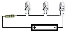
With that i calc
15V-3.2V = 5.4V
5.4 V
/ .020 A
________
270 Ohms
Edit:
Oh wait...are you going by 1 led and 1 resistor for your calcs
If i didnt mention this, i think i did but not sure, im running the leds in a string of 3 each with a resistor. With that im running a 270 ohm in series with the leds
Sorta like this
With that i calc
15V-3.2V = 5.4V
5.4 V
/ .020 A
________
270 Ohms
Last edited by jeff5347; 05-23-2011 at 07:02 PM.
05-23-2011, 07:14 PM
#93
Senior Member
Thread Starter
iTrader: (4)
Join Date: Jul 2006
Location: Ontario, Canada
Posts: 5,548
Edit:
Oh wait...are you going by 1 led and 1 resistor for your calcs
If i didnt mention this, i think i did but not sure, im running the leds in a string of 3 each with a resistor. With that im running a 270 ohm in series with the leds
Sorta like this
With that i calc
15V-3.2V = 5.4V
5.4 V
/ .020 A
________
270 Ohms
If you're calculating at 3.2V, .020A, and 15V then you're running .108 Watts. Very safe territory, especialy considering your battery should never be charging over 14.4 V
Carry on, post pictures though. And 1/4 Watt is obviously fine for that application.
05-24-2011, 07:11 AM
#95
Senior Member
Join Date: Dec 2005
Location: Leicester, Ma
Posts: 1,124
Tuner, another question. GOt everythnig wired up and all works. I made some perf board for the lcd displays and used 3 leds in each with a 390 ohm resistor. Didnt want the lcd screen to be crazy bright. But when i test it out i get hot spots. Now i can live with it but i dont want to. Any ideas on fixing the hot spots. hould i go to the original resistor for 3 leds at 270. It will be brighter but will it hot spot more. What other ideas to make it a uniform light under the lcd screens?
Edit:
Just for more info. I would not like to buy any more leds or bulbs. I nee dto get this in today so i can drive.
The leds i have in now are 3 facing vertical at the cluster (facing up.)
Was thinking what if i took 2 and faced tham horizontal so there wouldnt be hot spots but it would captured the light in there.
ALso for note i have reflective tape in there to help mirror the light so maybe 2 horizontal would disperse the light evenly with the reflective tape. I didnt notice a difference with the tape with the 3 leds...
Last edited by jeff5347; 05-24-2011 at 08:47 AM.
05-24-2011, 07:23 PM
#96
Senior Member
Thread Starter
iTrader: (4)
Join Date: Jul 2006
Location: Ontario, Canada
Posts: 5,548
Tuner, another question. GOt everythnig wired up and all works. I made some perf board for the lcd displays and used 3 leds in each with a 390 ohm resistor. Didnt want the lcd screen to be crazy bright. But when i test it out i get hot spots. Now i can live with it but i dont want to. Any ideas on fixing the hot spots. hould i go to the original resistor for 3 leds at 270. It will be brighter but will it hot spot more. What other ideas to make it a uniform light under the lcd screens?
Edit:
Just for more info. I would not like to buy any more leds or bulbs. I nee dto get this in today so i can drive.
The leds i have in now are 3 facing vertical at the cluster (facing up.)
Was thinking what if i took 2 and faced tham horizontal so there wouldnt be hot spots but it would captured the light in there.
ALso for note i have reflective tape in there to help mirror the light so maybe 2 horizontal would disperse the light evenly with the reflective tape. I didnt notice a difference with the tape with the 3 leds...
Edit:
Just for more info. I would not like to buy any more leds or bulbs. I nee dto get this in today so i can drive.
The leds i have in now are 3 facing vertical at the cluster (facing up.)
Was thinking what if i took 2 and faced tham horizontal so there wouldnt be hot spots but it would captured the light in there.
ALso for note i have reflective tape in there to help mirror the light so maybe 2 horizontal would disperse the light evenly with the reflective tape. I didnt notice a difference with the tape with the 3 leds...
If it were me, I would get the HP3's, that's what I did for mine, I tested a few ways and the HP3 is cheaper, and it's a drop in for that location, it's just the best option...
05-25-2011, 10:16 AM
#97
Senior Member
Join Date: Dec 2005
Location: Leicester, Ma
Posts: 1,124
Hey Tuner, So i put the cluster back in last night and and 1 string of leds would go on and off when i put the car in a certain gear..ugh. ALso this short didnt let me shift the car (Auto) when iwanted to in would go from 1,2,3 even if i had the shifter in first. So i started sweating. SO i took it back out and found an led grounding out. So i overkilled on protecting all the solder and such so it is good to go. I reinstalled today and all works well.
I can say it gives a nice soft blue kinda like the hawiian ocean, kinda. Looks real nice. Now i cant wait to see it when it is all lit up tonight.
I will get pics tonight and post
I can say it gives a nice soft blue kinda like the hawiian ocean, kinda. Looks real nice. Now i cant wait to see it when it is all lit up tonight.
I will get pics tonight and post

 05-25-2011, 07:06 PM
#99
Senior Member
Thread Starter
iTrader: (4)
Join Date: Jul 2006
Location: Ontario, Canada
Posts: 5,548
Looks great jowo, I was wondering where you got to, haven't seen you in a bit on here! Your gauges were one of my first pushes to get mine done, I was trying to hold off on my LED mods in this car for a little, because i know where it leads, one thing to the next ha ha.
I think you should get some of the HP3's for your LCD's though man, the dots would drive me nuts!
I think you should get some of the HP3's for your LCD's though man, the dots would drive me nuts!
05-31-2011, 08:01 AM
#100
Newbie - Just Registered

Join Date: May 2011
Posts: 1
I just have a quick question I hope I didn't miss it in the prior posts but I just needed to know aside from the 4 T5 wedge types how many LEDs do you need to replace all stock lights in the gauges and which type are needed? In other cars I have used 5050 SMD LED s im assuming these are useable here?
06-02-2011, 07:12 AM
#101
Senior Member
Join Date: Dec 2005
Location: Leicester, Ma
Posts: 1,124
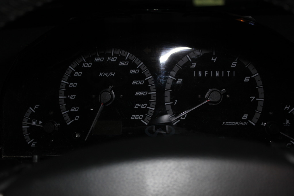
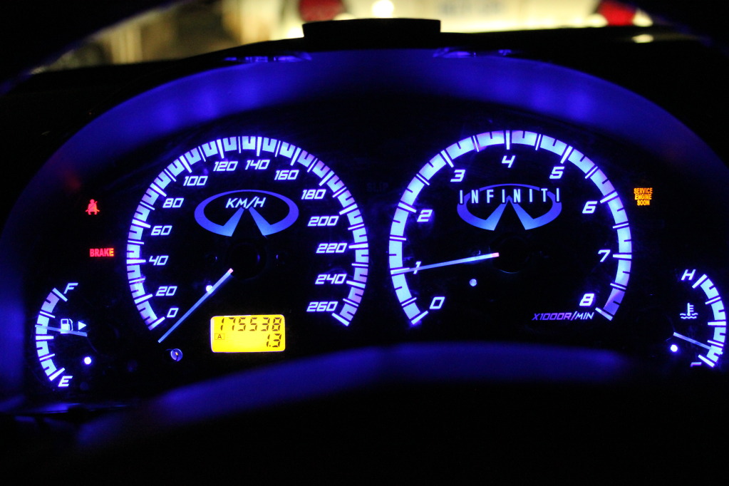
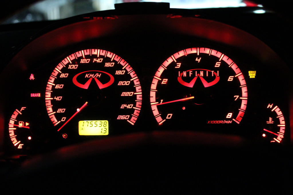
Ok so better late than never. Had a major virus than crashed my computer so now its back up. Anyways here are the pics of the LED cluster. In person the cluster looks amazing. No hotspots or flaws. In the pics for some reason it shows a few hotspots and a cold spot. The flaws it shows is at 0mph which i consider a cold spot. It is because i wasnt able to place the LED directly under the 0mph like i was with all the others. The other is the LCD display which shows half moons. In person they are there but no where near the effect the pics show. Well here are the pics


 06-27-2011, 07:13 PM
#104
Senior Member
Thread Starter
iTrader: (4)
Join Date: Jul 2006
Location: Ontario, Canada
Posts: 5,548
Yes, it's possible, it's been done, I haven't done one though, not worth the cost that it would take to do it on 98% of vehicles. A lot of wiring involved.


")
 )
02-15-2013, 06:12 PM
)
02-15-2013, 06:12 PM
#112
02-15-2013, 07:19 PM
#114


what did it cost him? Several hundred bucks in parts, along with several hundred hours of research, design, theory and fab, THEN more hours of assembly and fitment for the pro results you see here.

Thread
Thread Starter
Forum
Replies
Last Post
AaronL
5th Generation Maxima (2000-2003)
15
08-08-2020 10:31 AM
trsandrew
Group Deals / Sponsors Forum
2
10-25-2015 02:47 PM
bigfrank
4th Generation Maxima (1995-1999)
2
10-01-2015 12:51 PM