DIY Flush Mounted Voltmeter Installation
 06-18-2008, 09:04 PM
#1
Member
Thread Starter

Join Date: Jun 2006
Location: OC, CA
Posts: 56
DIY Flush Mounted Voltmeter Installation
Greetings.
I love voltmeters. They tell you if the alternator died and you are running on the battery. Or in our case, the voltage regulator died and the car's electrical system was seeing 18.6VDC. Luckily, the ECU survived. All cars should have a voltmeteer, and since El Maximo didn't, DIY to the rescue.
Car is 2001 SE AE with AT. Gauge is Cyberdyne A000E160N green LED digital voltmeter with adjustable hi/ lo warning, about $40 online. I saw no need to adjust the hi/ lo flashing display set points. This particular gauge would dim when the running lights were turned on, but would not go back to the full bright display if the running lights were turned back off. So, I simply ran the gauge on full bright and used a small piece of window tint I picked up off the floor at the local window tint shop. Drove over there, saw a small piece on the ground, asked if I could have it, and it was mine.
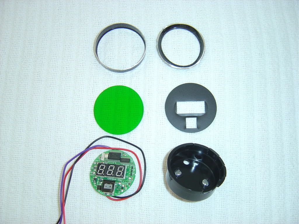
It all starts here:
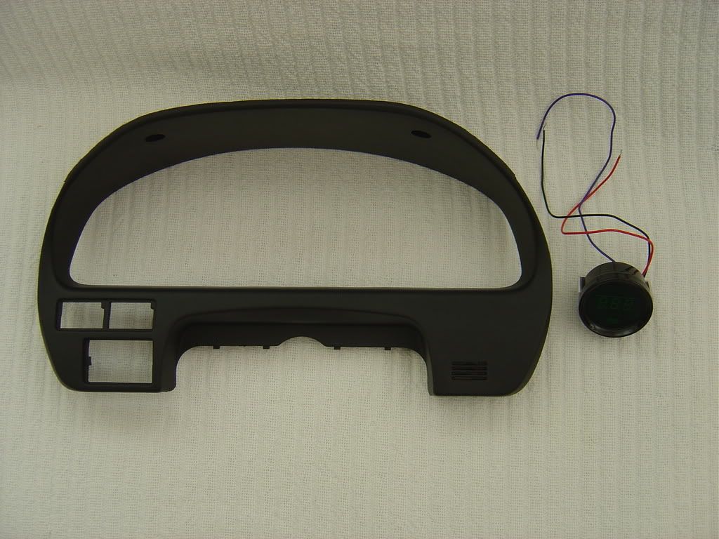
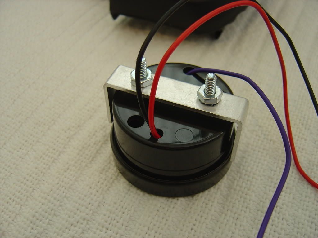
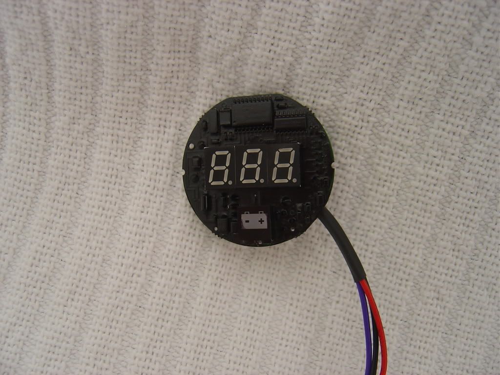
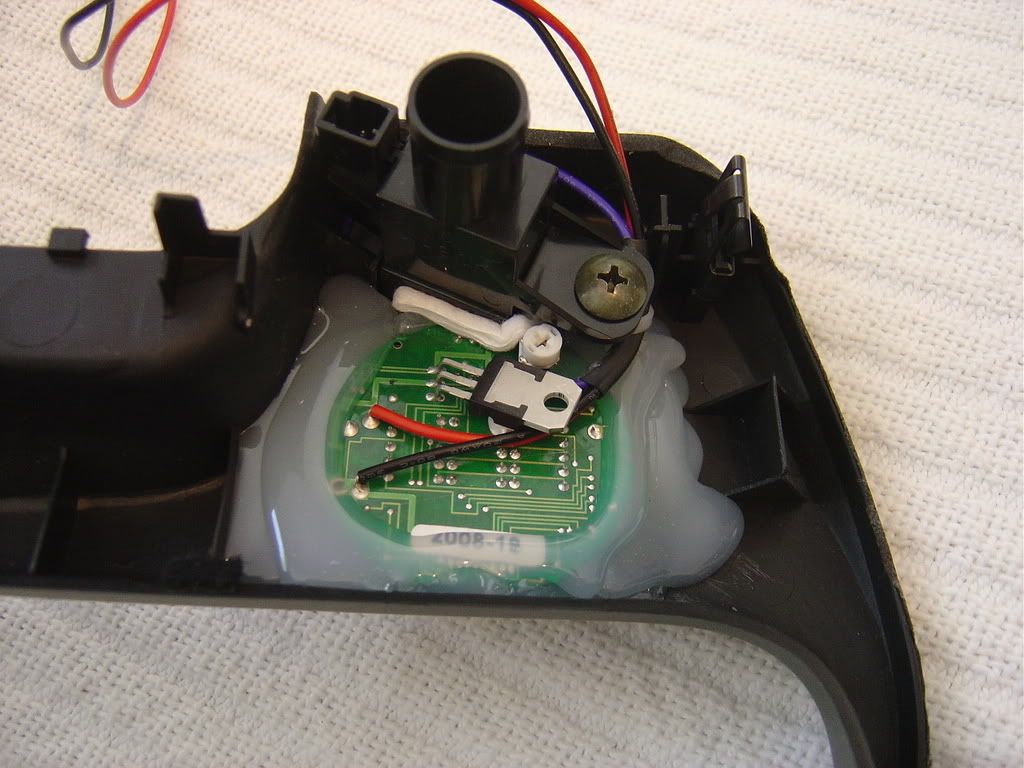
Back of the gauge. Black is ground, red is positive, purple is for dimming (didn't use):
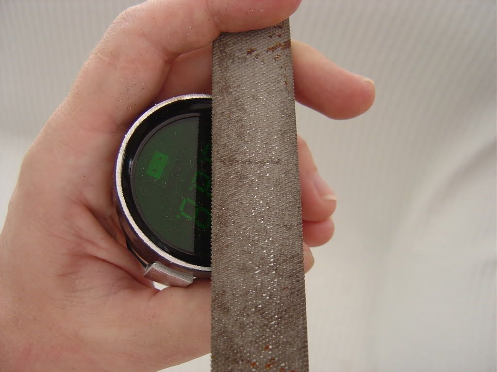
Cutting the gauge case open:
Pull:
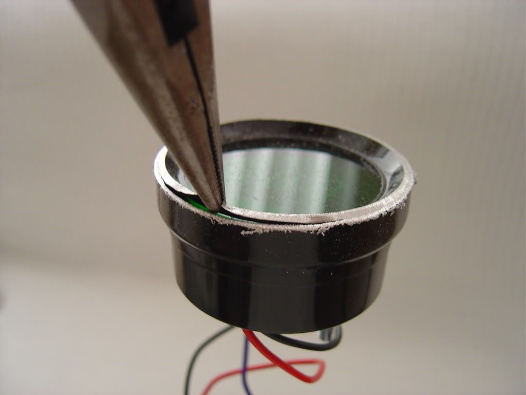
Disassembled; only the circuit board and the green lens get used:
Continued below...
I love voltmeters. They tell you if the alternator died and you are running on the battery. Or in our case, the voltage regulator died and the car's electrical system was seeing 18.6VDC. Luckily, the ECU survived. All cars should have a voltmeteer, and since El Maximo didn't, DIY to the rescue.
Car is 2001 SE AE with AT. Gauge is Cyberdyne A000E160N green LED digital voltmeter with adjustable hi/ lo warning, about $40 online. I saw no need to adjust the hi/ lo flashing display set points. This particular gauge would dim when the running lights were turned on, but would not go back to the full bright display if the running lights were turned back off. So, I simply ran the gauge on full bright and used a small piece of window tint I picked up off the floor at the local window tint shop. Drove over there, saw a small piece on the ground, asked if I could have it, and it was mine.
It all starts here:
Back of the gauge. Black is ground, red is positive, purple is for dimming (didn't use):
Cutting the gauge case open:
Pull:
Disassembled; only the circuit board and the green lens get used:
Continued below...
Last edited by AJ~; 06-18-2008 at 10:18 PM.
 06-18-2008, 09:05 PM
#2
Member
Thread Starter
Join Date: Jun 2006
Location: OC, CA
Posts: 56
Continued:
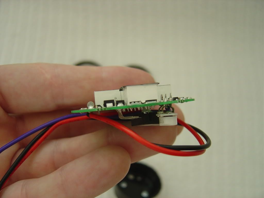
Thin!
Mask it:
Paint it:
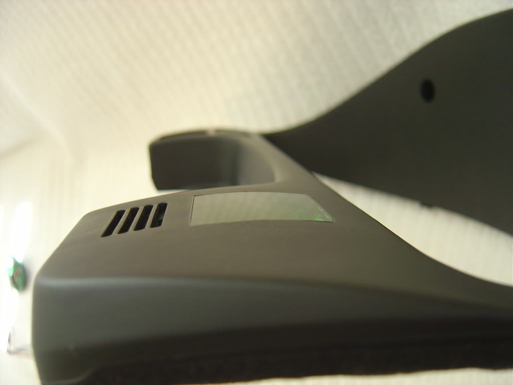
Now the fun part. The green plastic lens was warmed on a teflon pan in the oven, then quickly removed and allowed to cool off on the instrument cluster cover to form to the cover's shape. Mild pressure was used to keep the lens on the cover. A square hole was measured and transferred to the instrument cluster cover. Using a drill, exacto knives, files of various sizes and tooth shape, and sand paper, a perfectly square opening was made in the instrument cluster cover. Then the lens was cut to fit, taking a tiny bit off at a time to insure a perfect friction fit. Super glue was used to permanently attach the lens to the cover. Capillary action draws the glue into the tight joint. The water-thin super glue dries, shrinks, then more super glue is applied. Did this three times. Rock solid and it is perfectly flush, better than what is seen in this picture:
Hot glue gun is your friend:
Continued below...
Thin!
Mask it:
Paint it:
Now the fun part. The green plastic lens was warmed on a teflon pan in the oven, then quickly removed and allowed to cool off on the instrument cluster cover to form to the cover's shape. Mild pressure was used to keep the lens on the cover. A square hole was measured and transferred to the instrument cluster cover. Using a drill, exacto knives, files of various sizes and tooth shape, and sand paper, a perfectly square opening was made in the instrument cluster cover. Then the lens was cut to fit, taking a tiny bit off at a time to insure a perfect friction fit. Super glue was used to permanently attach the lens to the cover. Capillary action draws the glue into the tight joint. The water-thin super glue dries, shrinks, then more super glue is applied. Did this three times. Rock solid and it is perfectly flush, better than what is seen in this picture:
Hot glue gun is your friend:
Continued below...
Last edited by AJ~; 06-18-2008 at 10:46 PM.
06-18-2008, 09:06 PM
#3
Member
Thread Starter
Join Date: Jun 2006
Location: OC, CA
Posts: 56
Concluded:
Finished!
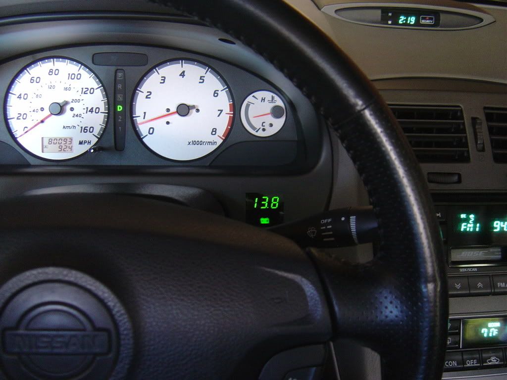
If I did it again, I would use dark tinted 3/16" thick acrylic plastic. Other than that, I am very happy with the results!
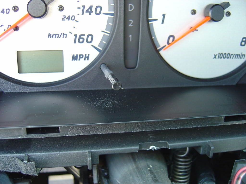
While I was in there, I removed the clear plastic cover from the instrument cluster and removed the dust that made it's way inside through the hole that the trip meter reset button passes through. You know, this dust:
-AJ
Finished!
If I did it again, I would use dark tinted 3/16" thick acrylic plastic. Other than that, I am very happy with the results!
While I was in there, I removed the clear plastic cover from the instrument cluster and removed the dust that made it's way inside through the hole that the trip meter reset button passes through. You know, this dust:
-AJ
Last edited by AJ~; 06-18-2008 at 09:12 PM.


 06-18-2008, 10:09 PM
#7
Member
Thread Starter
Join Date: Jun 2006
Location: OC, CA
Posts: 56
Am I still a noob? Does post count make the man? Am I OG?
I was sooooo pissed when the voltage regulator died. Wife was driving behind me when it happened and she calls me on the cell and says, honey, the dashboard just turned into a Christmas tree. So, I say ok, follow me and we'll get off the freeway and I will take a look at it. We did, I decide the alternator died and she is now running on the battery, tell her to open the windows and sweat, turn off everything electrical, and continue on our way to drop off my company car and then drive home.
Go on vacation overseas. Come home three weeks later. Put voltmeter to battery, start car and see 18.6VDC! Spend day off finding rebuilt alternator, scratch up arms and hands installing, and vow to finally get around to installing a voltmeter.
Said this: ^@#$%, and this: *&+>$, followed by a whole lot of these: ~}*(^%$! when installing the alternator.
-AJ
I was sooooo pissed when the voltage regulator died. Wife was driving behind me when it happened and she calls me on the cell and says, honey, the dashboard just turned into a Christmas tree. So, I say ok, follow me and we'll get off the freeway and I will take a look at it. We did, I decide the alternator died and she is now running on the battery, tell her to open the windows and sweat, turn off everything electrical, and continue on our way to drop off my company car and then drive home.
Go on vacation overseas. Come home three weeks later. Put voltmeter to battery, start car and see 18.6VDC!
Spend day off finding rebuilt alternator, scratch up arms and hands installing, and vow to finally get around to installing a voltmeter.Said this: ^@#$%, and this: *&+>$, followed by a whole lot of these: ~}*(^%$! when installing the alternator.
-AJ

 06-18-2008, 10:41 PM
#9
Member
Thread Starter
Join Date: Jun 2006
Location: OC, CA
Posts: 56
Forgot to add this:
In the picture "Hot glue gun is your friend" you can see that the climate control temperature intake has a wad of cotton between it and the voltmeter's circuit board. The corner of the intake was cut off to clear the circuit board, and a round cotton make-up removal pad (thanks honey!) was folded in half, cut to shape, then placed between the intake and the circuit board to seal it up. Simple and effective. Use whatever you want to seal it. Just seal it so the automatic climate control system is sucking air from the passenger compartment and not from inside the hot dash board.
-AJ

 don't get me wrong somethings I do


 06-19-2008, 08:34 PM
#18
Member
iTrader: (4)

Join Date: Sep 2005
Location: Long Beach, CA is where i live. Queens NYC is always home.
Posts: 297
Nice and CLEAN mod yo. I gotta try somethin like that on my 3rd gen.Mayby put the volt guage where the clock is now. I got a clock in my radio so who cares bout the OEM clock right ???


 thanks n nice work!
06-20-2008, 12:32 AM
thanks n nice work!
06-20-2008, 12:32 AM
#20
Member
Thread Starter
Join Date: Jun 2006
Location: OC, CA
Posts: 56


 06-20-2008, 05:48 AM
#22
http://maxima.theowensfamily.com/audiowiring.asp
If you wanted to get the Dimmer working you can use this wire behind the headunit
Red with Yellow Stripe...
VERY nice job! It def. looks OEM.
If you wanted to get the Dimmer working you can use this wire behind the headunit
Red with Yellow Stripe...
VERY nice job! It def. looks OEM.


 06-20-2008, 10:56 AM
#29
Member
Thread Starter
Join Date: Jun 2006
Location: OC, CA
Posts: 56
http://maxima.theowensfamily.com/audiowiring.asp
If you wanted to get the Dimmer working you can use this wire behind the headunit
Red with Yellow Stripe...
VERY nice job! It def. looks OEM.
If you wanted to get the Dimmer working you can use this wire behind the headunit
Red with Yellow Stripe...
VERY nice job! It def. looks OEM.
The dimming function on the Cyberdyne gauge is two-stage hi/low: when voltage is applied to the red wire, the voltmeter powers up at full bright. Add power to the purple wire and the gauge "dims" down to a preset lower level of brightness (which was actually too bright anyway). It is suppossed to go back to the high brightness mode when power is removed from the purple wire. Mine would not (defective?) do this. Dim yes, return to full bright no. Hence, the little piece of window tint I wrote about.
Actually happy with it like this!
-AJ


 11-10-2008, 04:15 PM
#36
very nice, came out looking great and also the write up is excellent! What did you run the wires to (somewhere in the fuse box?).
I have a scangauge wired up that reports battery voltage which is another option.
I have a scangauge wired up that reports battery voltage which is another option.
 11-11-2008, 12:03 PM
#39
Senior Member

Join Date: Oct 2006
Posts: 604
wiring & time to comlete
Also, how long might this job take to complete? I suppose it depends on how fussy one is, but better part of a Saturday seems like it???
