O2 Simulator Installation
 04-18-2006, 09:12 PM
#1
Supporting Maxima.org Member

Thread Starter
iTrader: (48)
Join Date: Apr 2004
Location: Fairfax, VA
Posts: 16,555
O2 Simulator Installation
USE THIS WRITE-UP AT YOUR OWN RISK, I AM NOT RESPONSIBLE FOR ANY DEATH/INJURY/DAMAGE SUSTAINED BY YOUR USING THIS
O2 Simulator Installation (this is really just a rehash of BlackbirdVQ's write-up but for the fact that I included pictures that I took tonight)
This should work on all Cali spec Maximas. When dealing with codes P0420 and P0430, whether its voluntary removal of or just bad pre-cats, the O2 sim helps keep your SES/CEL/MIL light off and typically also prevents the ECU from storing any related codes. Rear 02 sensors only monitor if the cats work and do not affect the long or short trim fuel so basically, they do not affect drivability or the air/fuel ratio. Since the ECU is monitoring catalyst efficiency using the rear O2 sensors and the O2 sim simulates the proper voltage for the ECU to think that the cats are working. For more info, see www.o2sim.com.
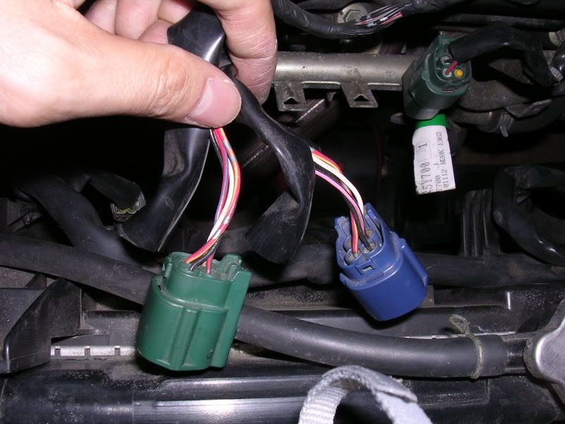
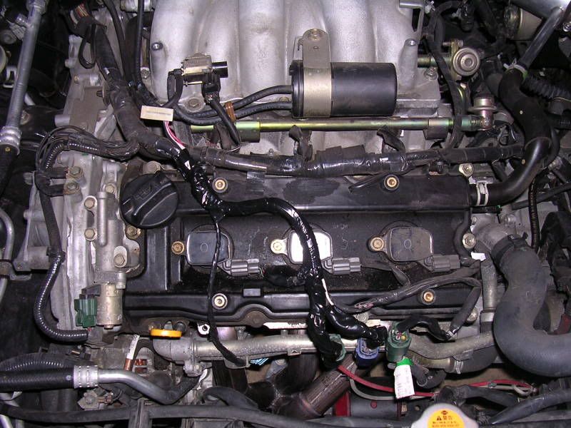
The wires tapped into are the wires BEFORE the connectors for the rear/downstream/secondary O2 sensors (so the length of wiring going from the ECM to the connectors). The dark blue connector connects to the WHITE wire shroud/harness and this is for the Bank 1 (rear bank) downstream O2 sensor. The green connector connects to the RED wire shroud/harness and is for the Bank 2 (front bank) downstream O2 sensor. Cut back the black wrap before each connector and you should see 4 wires:
Black: Ground
White: Signal
Red/Yellow: Power
Red/Blue: Heater
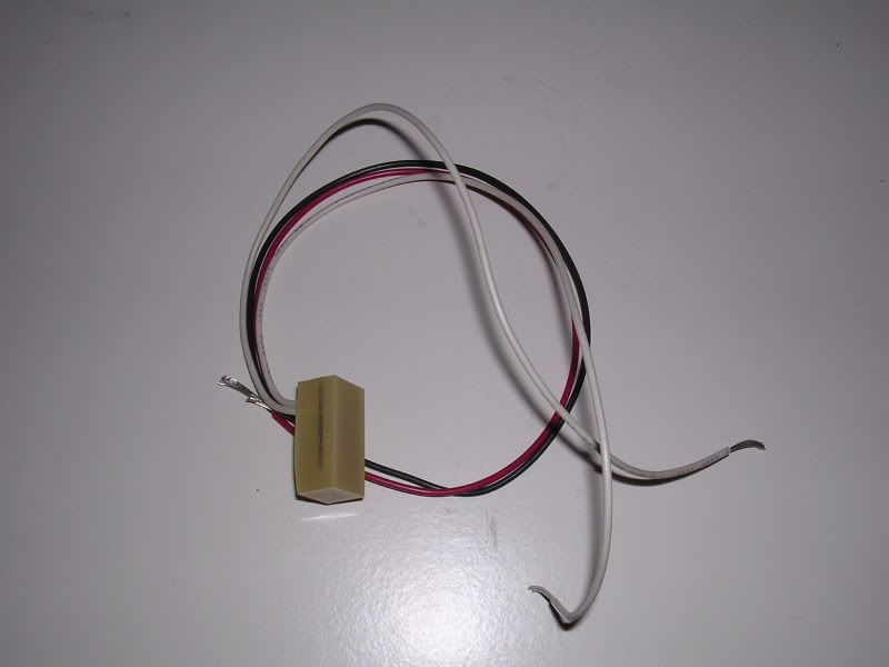
If you are going to simulate BOTH secondary O2 sensors, be sure to have bought a dual output sim with one black wire (ground), one red wire (power), and two white wires (signal).
The installation for a single output sim is the same, except you just tap into the signal of the sensor you want to simulate instead of both.
On ONE O2 sensor harness:
Using a wire stripper, strip about half an inch to expose the copper wires under the ground and power wires.
Tap the black wire from the O2 sim to the black (ground) wire.
Tap the red wire from the O2 sim to the red/yellow (power) wire.
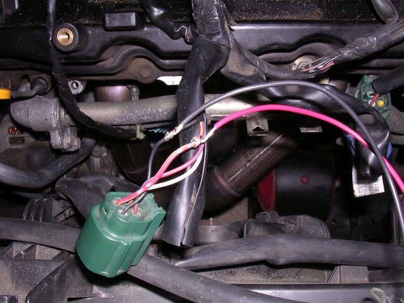
Cut the white signal wire and connect one of the white wires from the O2 sim to the end that is going back to the ECU.
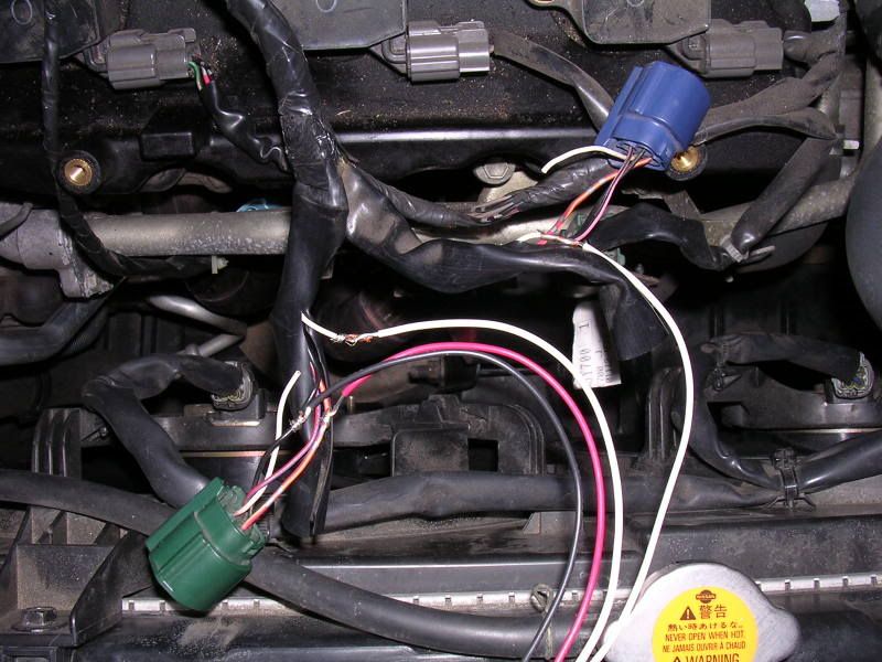
On the other O2 sensor harness:
Cut the white signal wire and connect the second white wire from the O2 sim to the end that is going back to the ECU.
Heater wires:
Leave em intact and both secondaries plugged into their respective connectors, the ECU still needs to read these or it will throw a code for heater malfunction or something.
You can now either solder the joints and wrap them up in heatshrink or electrical tape, or you can clear the codes and start the car to see if the sim is doing its job before soldering. The yellow LED on the sim should be blinking when the car is on/running.
Other links:
BlackbirdVQ's write-up: http://forums.maxima.org/showthread.php?t=361017
If you want to completely remove and simulate your secondary O2 sensors, even the heater wires: http://forums.maxima.org/showthread.php?t=435399
O2 Simulator Installation (this is really just a rehash of BlackbirdVQ's write-up but for the fact that I included pictures that I took tonight)
This should work on all Cali spec Maximas. When dealing with codes P0420 and P0430, whether its voluntary removal of or just bad pre-cats, the O2 sim helps keep your SES/CEL/MIL light off and typically also prevents the ECU from storing any related codes. Rear 02 sensors only monitor if the cats work and do not affect the long or short trim fuel so basically, they do not affect drivability or the air/fuel ratio. Since the ECU is monitoring catalyst efficiency using the rear O2 sensors and the O2 sim simulates the proper voltage for the ECU to think that the cats are working. For more info, see www.o2sim.com.
The wires tapped into are the wires BEFORE the connectors for the rear/downstream/secondary O2 sensors (so the length of wiring going from the ECM to the connectors). The dark blue connector connects to the WHITE wire shroud/harness and this is for the Bank 1 (rear bank) downstream O2 sensor. The green connector connects to the RED wire shroud/harness and is for the Bank 2 (front bank) downstream O2 sensor. Cut back the black wrap before each connector and you should see 4 wires:
Black: Ground
White: Signal
Red/Yellow: Power
Red/Blue: Heater
If you are going to simulate BOTH secondary O2 sensors, be sure to have bought a dual output sim with one black wire (ground), one red wire (power), and two white wires (signal).
The installation for a single output sim is the same, except you just tap into the signal of the sensor you want to simulate instead of both.
On ONE O2 sensor harness:
Using a wire stripper, strip about half an inch to expose the copper wires under the ground and power wires.
Tap the black wire from the O2 sim to the black (ground) wire.
Tap the red wire from the O2 sim to the red/yellow (power) wire.
Cut the white signal wire and connect one of the white wires from the O2 sim to the end that is going back to the ECU.
On the other O2 sensor harness:
Cut the white signal wire and connect the second white wire from the O2 sim to the end that is going back to the ECU.
Heater wires:
Leave em intact and both secondaries plugged into their respective connectors, the ECU still needs to read these or it will throw a code for heater malfunction or something.
You can now either solder the joints and wrap them up in heatshrink or electrical tape, or you can clear the codes and start the car to see if the sim is doing its job before soldering. The yellow LED on the sim should be blinking when the car is on/running.
Other links:
BlackbirdVQ's write-up: http://forums.maxima.org/showthread.php?t=361017
If you want to completely remove and simulate your secondary O2 sensors, even the heater wires: http://forums.maxima.org/showthread.php?t=435399

 04-18-2006, 09:26 PM
#3
Supporting Maxima.org Member
Thread Starter
iTrader: (48)
Join Date: Apr 2004
Location: Fairfax, VA
Posts: 16,555
Btw, I was throwing a CEL for P0037 and P0057 (I did the self diagnose procedure and counted the SES/CEL blinks) codes before, since my secondaries were completely unplugged and off the car. After installing the dual output sim and reseting the ECU (the procedure was a pain in my ****), the CEL is gone. I still have to drive it around some to make sure it stays off, so we'll see how that works out.
And yes, my secondary O2s are just ziptied under my engine cover.
And yes, my secondary O2s are just ziptied under my engine cover.
 04-19-2006, 07:11 AM
#5
Supporting Maxima.org Member
Thread Starter
iTrader: (48)
Join Date: Apr 2004
Location: Fairfax, VA
Posts: 16,555
Originally Posted by Gapp
So if I plugged my secondary O2 back into its harness, and left the heater wire untapped, tapping the 12v, ground, and signal, I could let the O2 "hang" outside the exhaust w/o a SES?
04-19-2006, 08:19 AM
#6
So a resistor is only needed if the sensor is not hooked up at all to the harness? The reason I ask is because I disconnected my sensor and ruined it trying to take it out of the bung. It's the rear aft. cat (fed spec) sensor so luckily I only throw a SES with no other issues. I don't have the sensor anymore. If I'm not mistaken, I can hook a resistor up to ground on one end and to the heater wire on the other. (And I thought I was over with experimenting ") )
)
)
04-19-2006, 08:34 AM
#7
Supporting Maxima.org Member
Thread Starter
iTrader: (48)
Join Date: Apr 2004
Location: Fairfax, VA
Posts: 16,555
Originally Posted by Gapp
So a resistor is only needed if the sensor is not hooked up at all to the harness?
For more info on completely removing the O2 sensor (not having it plugged into the harness), see the thread I linked to in the All Motor forum.
04-19-2006, 09:55 AM
#8
Puppetmaster - Great write-up and nice pics too!
One note I would like to mention is that you may not need to tap into the main wiring harness before the connector going to the sensor. I installed mine by tapping into the wiring after the connector, just before the sensor itself and the simulator works fine. I used a single output sim on the secondary O2 after the main cat on fed spec...
One note I would like to mention is that you may not need to tap into the main wiring harness before the connector going to the sensor. I installed mine by tapping into the wiring after the connector, just before the sensor itself and the simulator works fine. I used a single output sim on the secondary O2 after the main cat on fed spec...
04-19-2006, 10:13 AM
#9
Supporting Maxima.org Member
Thread Starter
iTrader: (48)
Join Date: Apr 2004
Location: Fairfax, VA
Posts: 16,555
Originally Posted by igzy
Puppetmaster - Great write-up and nice pics too!
One note I would like to mention is that you may not need to tap into the main wiring harness before the connector going to the sensor. I installed mine by tapping into the wiring after the connector, just before the sensor itself and the simulator works fine. I used a single output sim on the secondary O2 after the main cat on fed spec...
One note I would like to mention is that you may not need to tap into the main wiring harness before the connector going to the sensor. I installed mine by tapping into the wiring after the connector, just before the sensor itself and the simulator works fine. I used a single output sim on the secondary O2 after the main cat on fed spec...
The main reasons for my doing the tapping and cutting before the harnesses are:
1. It it will be easier to cover up when I go back to stock since all I have to do is remove the sim and tape everything back up (and resolder the white wires). When you have to rejoin O2 sensor wires, its hard to fit the colored shroud/wrap back over the joints (unless you can do it with really thin layer of solder and thin heatshrink/tape). Then again, I'm not an expert with soldering, so maybe you people who are good at this won't face this issue. I just think leaving the O2 sensors intact is a good thing.
I also liked how neatly I could tape the sim back with the wiring.
2. I find that the copper wires before the harness are much easier to work with than the steel or whatever wires on the O2 sensor itself. I cut off one of my O2 sensor's wires, and I hated soldering those slippery wires back together. So I would just rather not have to deal with the O2 sensor wires as far as possible. And once again, maybe those better at dealing with such wiring may not find this a problem.
04-19-2006, 12:36 PM
#10
You brought up some good points there. I guess that would work the best for cases when sensors need to be extended or there are no holes provided for them (in cases of headers and Y upgrades)...
My case is slightly different in that the sensor itself went bust and I couldn't remove it (nicely welded in) so I decided to tap into the sensor wire instead of the main harness as I didn't want to mess with the main too much and in case I get a torch that I can pull out the sensor itself and replace it properly only the sensor would be affected (as wires would get replaced with it). Besides, I did not solder anything, I used quick-tap connectors with some insulation tape and it works like a charm...
In any case, you did an outstanding job in describing how it can be done!
04-19-2006, 01:16 PM
#11

Here is my addition to the pictures. This is from my install.
#1 Picture of closeup of connector
#2 Pic of heat shield after cutting
#3 Pic of wire pulled out
#4 Pic of Heater wire separated


#1 Picture of closeup of connector
#2 Pic of heat shield after cutting
#3 Pic of wire pulled out
#4 Pic of Heater wire separated
04-19-2006, 01:20 PM
#12
#5 Close up of heater wire seperated Bank 1 (I think)
#6 Close up of heater wire separated Bank 2 (I think)
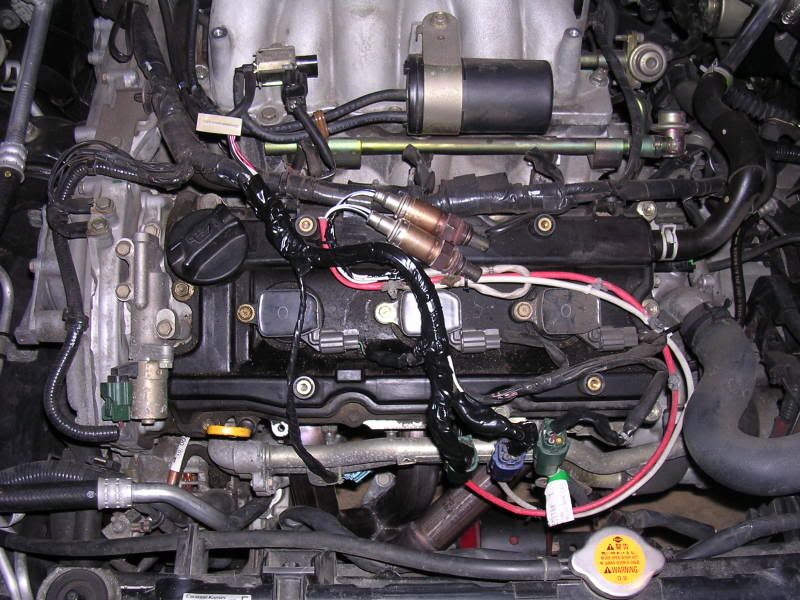
#7 Finished product (got hasty wanting to finish this project so I didn't take any shots of the soldering)


#6 Close up of heater wire separated Bank 2 (I think)
#7 Finished product (got hasty wanting to finish this project so I didn't take any shots of the soldering)
05-01-2006, 11:59 AM
#14

so i got the simulator from cattmans. is the led suppost to blink or stay on? i just want to make sure the simulator is working. i have a cel light on now but thats because i installed the simulator after i was driving around with the headers. so i think i need to do the reset procedure but that takes like 6 hrs so i will do it when i go to bed. so yeah, is my simulator light suppost to stay on? or blink? cause thats what its doing.
07-11-2006, 09:08 PM
#16
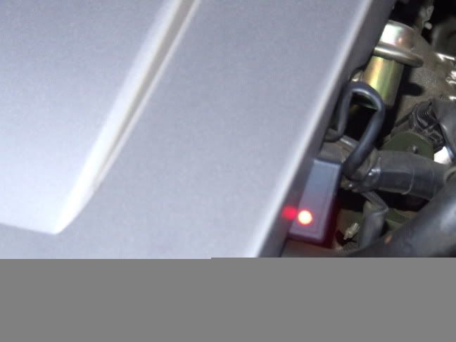
Got a question. During a smog test, does the cover get pulled off, meaning the engine cover? Just curious. If they saw my o2 sim like this pic below, would they say something? Should it be "tucked" under the cover? Just curious so I can be prepared in the next few years.
04-16-2007, 10:45 AM
#17
Newbie - Just Registered

Join Date: Feb 2007
Posts: 2
Hi guys, I'm just kinda visiting in because i am considering buying a maxima, either 02 or 03. All of this 02 sim stuff is cool, but i am just wondering (because it works on sentras) can you just use and 02 sensor spacer? Since i have not found it on this forum, you just use 2 spark plug non foulers and drill one out to fit the 02 sensor, and plug it in to the undrilled one, and after you put it back on the aftermarket headers the 02 sensor recieves less exhaust because of the spacer and does not throw a code. This works for almost all sentras, and wrx owners use it too. just wondering if this would work for a maxima too because it literally takes about 5 minutes and 4 dollars to make one and they work great. Instead of spending like an hour rigging up wiring. Thanks guys!
04-16-2007, 10:54 AM
#18
Supporting Maxima.org Member
Thread Starter
iTrader: (48)
Join Date: Apr 2004
Location: Fairfax, VA
Posts: 16,555
Yeah, the fouler is great and works on VWs too. The issue isn't so much as to whether we can use the foulers, its that aftermarket headers for these cars do not have bungs for the secondary O2s. You could add bungs, but that would cost you more than a $20 O2 sim. And IMO, it really does not take an hour and I'd hardly call the install "rigging up wiring". Trust me, it is really easy to do.
But anyways, for people who are doing this to solve a CEL, and who still have the stock y-pipe in place, my guess is that the fouler/spacer method could possibly work. I'm not sure if anyone around here has tried that yet.
But anyways, for people who are doing this to solve a CEL, and who still have the stock y-pipe in place, my guess is that the fouler/spacer method could possibly work. I'm not sure if anyone around here has tried that yet.
04-19-2007, 05:28 PM
#19
Newbie - Just Registered

Join Date: Dec 2006
Posts: 11
Simulator Install
Hello Puppetmaster,
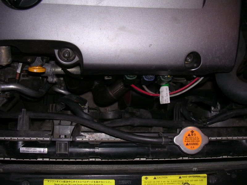
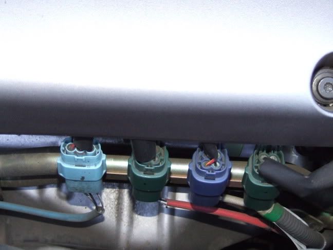
I was talking to you a few months ago about installing o2 simulator. I just got one from www.o2sim.com. After reading your post I have a few questions. Your post is for your 2002 maxima. I have 2001 maxima. The connector colors are a little different. See attached picture. I am getting the P0420 code. (Secondary sensor Bank 1 is third connector from left). The wire harness at bottom of connector is white. The 4 wires coming out the top of connector are (White - Black - Pink - Red/Yellow). Am I correct in saying the following. (White = SIGNAL) (Black = GROUND) (Pink = HEATER) (Red/Yellow = POWER). I can follow your post for hooking simulator to connector. I just need to know if I am labeling the 4 wires correctly.
Thanks,
Pugman
05-12-2007, 05:26 AM
#20
im sure youve read this: http://forums.maxima.org/showthread....ighlight=P0430
Seems like it will help the problem. Go for it, watch out for an o2 sensor going bad next. I need a new heated o2 sensor or a resistor and ive only had my sim in for 3 months. Currently have P0154, P0152 and P1168. Others have had better luck though. Hope all goes well.
Seems like it will help the problem. Go for it, watch out for an o2 sensor going bad next. I need a new heated o2 sensor or a resistor and ive only had my sim in for 3 months. Currently have P0154, P0152 and P1168. Others have had better luck though. Hope all goes well.
05-16-2007, 12:17 PM
#21
Supporting Maxima.org Member
Thread Starter
iTrader: (48)
Join Date: Apr 2004
Location: Fairfax, VA
Posts: 16,555
Originally Posted by Gennady7
I am guessing that one person did this and everyone else is confused?
Does anyone know which sensor to purchase?
Does anyone know which sensor to purchase?
That being said, have you looked into the root cause of the problem? ie. the precat (or O2 sensor) that is tripping the DTC? Just curious...
05-16-2007, 01:50 PM
#22
Donating Maxima.org Member

Join Date: Jul 2004
Posts: 701
Originally Posted by Puppetmaster
The dual ouput sim is used to simulate the secondaries for both front and rear banks. You can probably get away with a single output sim since you only have a code for the front bank precat.
That being said, have you looked into the root cause of the problem? ie. the precat (or O2 sensor) that is tripping the DTC? Just curious...
That being said, have you looked into the root cause of the problem? ie. the precat (or O2 sensor) that is tripping the DTC? Just curious...
I dont have the money for it right now and would prefer to get the dual output O2 simulator in case the pre-cat goes too.
Thanks
Gene
Just wondering, the model I listed as the dual output sim is what I need to get the job done?
05-17-2007, 10:47 AM
#23

I installed an O2 sim that I made using some circuit diagrams on the web on my G20. Work great (almost a year now).
I just wanted to throw out the suggestion that you install the Sim inside the cabin, right next to the ECU. This way saves you're engine bay harness from prying eyes, makes for a 'cleaner' install and keeps the Sim out of the elements. I know some of those Ebay sims don't look any better than the circuit I soldered up, and may not hold up under the various temps/ water, found in the engine bay.
All you need is the ECU pinouts from the FSM, and splice in your signal wires from there... Just an idea.
05-20-2007, 10:52 PM
#24
Donating Maxima.org Member
Join Date: Jul 2004
Posts: 701
Originally Posted by LoSt180
I installed an O2 sim that I made using some circuit diagrams on the web on my G20. Work great (almost a year now).
I just wanted to throw out the suggestion that you install the Sim inside the cabin, right next to the ECU. This way saves you're engine bay harness from prying eyes, makes for a 'cleaner' install and keeps the Sim out of the elements. I know some of those Ebay sims don't look any better than the circuit I soldered up, and may not hold up under the various temps/ water, found in the engine bay.
All you need is the ECU pinouts from the FSM, and splice in your signal wires from there... Just an idea.
I just wanted to throw out the suggestion that you install the Sim inside the cabin, right next to the ECU. This way saves you're engine bay harness from prying eyes, makes for a 'cleaner' install and keeps the Sim out of the elements. I know some of those Ebay sims don't look any better than the circuit I soldered up, and may not hold up under the various temps/ water, found in the engine bay.
All you need is the ECU pinouts from the FSM, and splice in your signal wires from there... Just an idea.
Also, does anyone know if Pugman labeled the sensors correctly for the 2000/2001 maxima?
Thanks guys!
05-23-2007, 03:06 AM
#25
Supporting Maxima.org Member
Thread Starter
iTrader: (48)
Join Date: Apr 2004
Location: Fairfax, VA
Posts: 16,555
Sent you a PM but I'll also post it here for others' benefit...
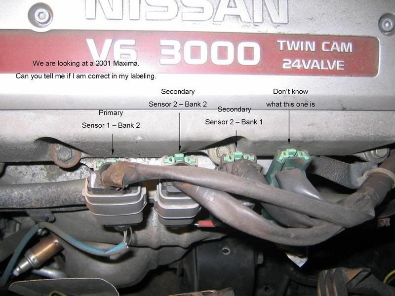
Looks like the picture from Pugman is correct, based on the position of the O2 sensors, but double check the colors based on the second diagram, which is from the TSB. Reason being I've seen O2 sensors have their positions switched around for whatever reason, either by the owner or dealer, and so the "middle two" aren't always the secondaries.
The colors indicated in the TSB diagram refer to the color of the wire shroud under the heat wrap. You can sort of see the red of Bank 2 Sensor 2 in the photo. The other one should be white.
Hope this helps.

Let me know if you have more questions...
Looks like the picture from Pugman is correct, based on the position of the O2 sensors, but double check the colors based on the second diagram, which is from the TSB. Reason being I've seen O2 sensors have their positions switched around for whatever reason, either by the owner or dealer, and so the "middle two" aren't always the secondaries.
The colors indicated in the TSB diagram refer to the color of the wire shroud under the heat wrap. You can sort of see the red of Bank 2 Sensor 2 in the photo. The other one should be white.
Hope this helps.
Let me know if you have more questions...
09-29-2008, 07:12 PM
#27

 01-17-2009, 05:06 AM
#30

I just ordered a test pipe, and I'm going to order an 02 sim and I'm glad I found this guide. But I just want to make sure I do this right. I only need to simulate 1 02 sensor correct? And just follow the first part of the guide to do that? Just want some clarification. Thanks
01-17-2009, 06:50 AM
#31
Supporting Maxima.org Member
Thread Starter
iTrader: (48)
Join Date: Apr 2004
Location: Fairfax, VA
Posts: 16,555
I just ordered a test pipe, and I'm going to order an 02 sim and I'm glad I found this guide. But I just want to make sure I do this right. I only need to simulate 1 02 sensor correct? And just follow the first part of the guide to do that? Just want some clarification. Thanks
01-17-2009, 08:59 PM
#32
 02-08-2009, 03:40 PM
#33
Senior Member

Join Date: Jun 2005
Location: Philadelphia, PA
Posts: 2,898
bumpidy bump baby! just wanted to say that i did this today, and everything went pretty smoothly.. i twisted, capped and taped the ends of the 2 white wires, and just twisted and taped the connections between the red and black wires.. the green LED was blinking slowly, so i assume it's doing its job?
i went to autozone today to have the codes cleared, and i'm waiting for my SES light to come back on (for other reasons).. when it does, i'm gonna scan it to make sure the O2 sensor codes are gone, then tape up all the wires with electrical tape.. i wanted to leave the wires un-taped until i was sure that the O2 simulator was doing its job.. as of now, the wires are sitting loose under the engine cover, but all the connections are either taped or capped and taped.. it's ok if the insulated wires are left un-taped for the time being until the light comes back on, and i can scan it again right?
i went to autozone today to have the codes cleared, and i'm waiting for my SES light to come back on (for other reasons).. when it does, i'm gonna scan it to make sure the O2 sensor codes are gone, then tape up all the wires with electrical tape.. i wanted to leave the wires un-taped until i was sure that the O2 simulator was doing its job.. as of now, the wires are sitting loose under the engine cover, but all the connections are either taped or capped and taped.. it's ok if the insulated wires are left un-taped for the time being until the light comes back on, and i can scan it again right?
 02-09-2009, 05:48 AM
#35
Senior Member
Join Date: Jun 2005
Location: Philadelphia, PA
Posts: 2,898
ok.. well maybe somebody can tell me.. if i go to get it scanned today, will the O2 sensor codes show up if no SES light is on? I really wanna get these wires taped up, but i wanna be sure the simulator is working properly first
02-09-2009, 10:36 AM
#36
Supporting Maxima.org Member
Thread Starter
iTrader: (48)
Join Date: Apr 2004
Location: Fairfax, VA
Posts: 16,555
The codes don't always come back right away, neither does the CEL, so just drive around more to give it some time.
There is basically what they call "Two Trip Detection Logic" or something like that and if a DTC is picked up the first "trip", it won't trigger a CEL but the DTC is recorded to memory. Only if the issue is detected again on the second trip is the CEL triggered.
It also depends on the ECM readiness state after the codes have been cleared. It has to do some self-diagnostics before it diagnoses DTCs. This is why you can't just clear the codes and run to the inspection station, because the system readiness test (SRT) will say it is incomplete and the tester will reject the vehicle until the SRT is complete. For the SRT to be complete, there is a mix of driving conditions that has to be met, but I can't remember exactly off the top of my head.
02-09-2009, 01:44 PM
#37


Basicly what do I need to buy to get rid of this? Remember I also have heaters.
Last edited by Revs2Hard; 02-09-2009 at 02:51 PM.
02-12-2009, 05:53 AM
#38
Supporting Maxima.org Member
Thread Starter
iTrader: (48)
Join Date: Apr 2004
Location: Fairfax, VA
Posts: 16,555
I have a 00 cali spec and Im wondering how many O2 sims I have to do? Im getting the P0430 code and want to get rid of it. Im also putting on a new Y-Pipe, dose that make a difference in how many I have to put in? Im also wondering do I have to pull the O2 sensors out after putting in the sim's or can I leave them in the exhaust? I dont have a huge engine cover to hide them under :-) LOL.
Basicly what do I need to buy to get rid of this? Remember I also have heaters.
Basicly what do I need to buy to get rid of this? Remember I also have heaters.
Along with the y-pipe, I'd just get a dual output sim to be safe. This will simulate working secondary sensors/proper cat functioning on both front and rear banks.
If you go with the dual output sim, you can leave the sensors in the bungs or take them out, it is up to you, but you need the harness connectors plugged in if not you will get a CEL for the heater circuits. In your case, I'd just leave em plugged in.
 02-15-2009, 10:58 AM
#40
Senior Member
Join Date: Jun 2005
Location: Philadelphia, PA
Posts: 2,898
ONE THING EVERYONE SHOULD KNOW ABOUT THIS INSTALL:
Be careful where you put your O2 sensors. Because they get REAL hot and start to burn through things... like wires... not that I would know from experience or anything...
Puppetmaster, you don't have a problem with your O2 sensors burning/melting anything under there?
Be careful where you put your O2 sensors. Because they get REAL hot and start to burn through things... like wires... not that I would know from experience or anything...
Puppetmaster, you don't have a problem with your O2 sensors burning/melting anything under there?
Last edited by wyche89; 02-15-2009 at 11:12 AM.