Cruise Control Not working After Clutch Job
 11-15-2012, 12:24 AM
#41

Don't get your hopes up. Those connectors by the fuse panel are the CONSULT and OBD II connectors. The cruise control module is on the other side of the steering column, about in line with the center console. It's not all that bad, the connector sticks out sort of in the open, but then after having to replace the air mix door motor, nothing is that bad. If that motor goes out again, I'm tossing in a couple gallons of gas followed by a lit match! Anyhow, back on topic.
I want to throw out some miscellaneous info. I checked part numbers of the ASCD Control module and the 97 & 98 use the same one, # 18930-0L700. The other years are different. The vacuum pump is the same for all years of the 4th gen, # 18955-40U00.
pic of ASCD control module

photo of ASCD vacuum pump

I want to throw out some miscellaneous info. I checked part numbers of the ASCD Control module and the 97 & 98 use the same one, # 18930-0L700. The other years are different. The vacuum pump is the same for all years of the 4th gen, # 18955-40U00.
pic of ASCD control module
photo of ASCD vacuum pump
Last edited by DennisMik; 11-15-2012 at 12:29 AM. Reason: fix typos
 11-19-2012, 08:22 AM
#43
Senior Member
Thread Starter

Join Date: Oct 2011
Location: Maine
Posts: 1,528
At this point, you will have to check signals on the cruise control control module to see if you have input signals and output signals. You will have to access to the cruise control module under the dash and check voltages on some pins. Use FSM page EL-150 as reference. I want to say up front that I have not checked these myself. I'm thinking of fixing the cruise control on my 97 so I can verify this as accurate.
The wire harness connectors are plugged in for checking.
pin 1 - green/orange stripe - 12 volts from steering wheel RESUME switch when pressed.
pin 2 - green/yellow stripe - 12 volts from steering wheel SET switch when pressed.
pin 4 - green/white stripe - 12 volts from dash switch when in the on position or you have the relay jumper.
Pin 5 - green/red stripe - 12 volts from the clutch & brake pedal switches, pedal not depressed, dash switch on.
pin 11 - red/green stripe - 0 volts from brake light switch, pedal not depressed.
The above pins can be checked while the car is sitting still. The engine does not have to be running, but the ignition switch has to be ON. After watching your video, I think they are working as they should be, but check them anyway.
The following pins, you would have to be driving the car at a speed where the cruise can operate, 30-90 mph.
pin 7 - pink/blue stripe - VSS signal from speedometer. Most likely a variable voltage depending on speed.
pin 8 - blue/white stripe - 12 volts to the vacuum pump motor, probably constant when the dashboard ON button has been pressed.
pin 9 - white/red stripe - 0 volts to make the make the vacuum pump motor run. This signal probably changes between 0 volts (motor runs) and 12 volts (motor not running) as the vacuum pump probably runs only when needed.
pin 10 - blue/yellow stripe - sends pump vacuum to actuator.
pin 14 - blue/red stripe - releases vacuum from actuator.
pins 10 and 14 control the amount of vacuum sent to the actuator. 0 volts when being used, 12 volts otherwise. the 0 volt reading is probably a short pulse and you may not see it with a voltmeter or a test light.
11-19-2012, 09:10 AM
#44
OK great, you're making progress. You have the needed conditions for the cruise to engage. So now the next part - is there a speed signal coming from the speedometer on pin 7 of the control unit and is the control unit sending power to the vacuum pump via pins 8 and grounding pin 9.
Before trying the drive and check voltages, you could go under the hood and put jumper wires on the vacuum pump and see if the motor runs. I think I'm going to go try this myself and see what I can see.
Before trying the drive and check voltages, you could go under the hood and put jumper wires on the vacuum pump and see if the motor runs. I think I'm going to go try this myself and see what I can see.
11-19-2012, 09:13 AM
#45
Senior Member
Thread Starter
Join Date: Oct 2011
Location: Maine
Posts: 1,528
OK great, you're making progress. You have the needed conditions for the cruise to engage. So now the next part - is there a speed signal coming from the speedometer on pin 7 of the control unit and is the control unit sending power to the vacuum pump via pins 8 and grounding pin 9.
Before trying the drive and check voltages, you could go under the hood and put jumper wires on the vacuum pump and see if the motor runs. I think I'm going to go try this myself and see what I can see.
Before trying the drive and check voltages, you could go under the hood and put jumper wires on the vacuum pump and see if the motor runs. I think I'm going to go try this myself and see what I can see.
11-19-2012, 09:36 AM
#46
Without looking at my car, you will have to go by wire colors. The pins you need to put jumper are diagonal from each other, not side by side. Unplug the connector from the pump so that you don't do any feedback to the control unit. 12 volts goes on the blue/white stripe wire and ground goes on the white/red stripe wire. Run a wire from the battery for the power and you can ground it anywhere.
Since I haven't done this, I can't say for sure if you will hear it. It is a small motor, so it probably won't be very loud. Maybe if you put your finger on the motor, you'll feel vibrations.
Since I haven't done this, I can't say for sure if you will hear it. It is a small motor, so it probably won't be very loud. Maybe if you put your finger on the motor, you'll feel vibrations.
Last edited by DennisMik; 11-19-2012 at 09:43 AM.
11-19-2012, 09:54 AM
#47
Senior Member
Thread Starter
Join Date: Oct 2011
Location: Maine
Posts: 1,528
I just jumped the pump and it does come on. You can hear it run...it sounds like one of those car air pumps. It didn't do anything else, like move the cable, but it does run which I think is a good sign.
11-19-2012, 04:16 PM
#48
The motor running is a good sign. I expected that the throttle cable would not move. There are 2 air valves/solenoids in the vacuum pump assembly, one to let vacuum into the actuator, the other to let air in. You would have to ground one of the other pins to make the make the vacuum valve work while the motor is running.
I tried to do this on my 2000 but the vacuum pump assembly is a little less accessible and I couldn't get both jumper wires on at the same time. After a half hour of laying on top of the engine I was pi$$ed off enough to unplug the connector from the ASCD control module and do it from that end. Getting your hands on the control module is not as easy in the 5th gen as it is in the 4th. Nissan swapped locations of the BCM and ASCD modules so I had to pull out the radio and heater controls.
Then I decided that rather than jumper the motor, I would check voltages on the control module pins while driving. The results were basically like I expected but not entirely, a case of theory and reality are not always the same. I checked 5 pins on the control module, the VSS signal and the 4 wires going to the vacuum pump. So here is my experience checking those 5 pins. Sorry if it is wordy, I hope you can understand it.
These readings were taken with the connector plugged in to the control module and the car being driven and using cruise control.
All voltage readings are DC volts with the exception of the VSS speed signal.
Note that because the engine was running, the car's alternator is charging and the voltage will be above 12 volts. Not all alternators output the same exact voltage as mine (14.1 volts). Any measurements you get would be a little different as a result of this.
Pin 7 pink/blue stripe
VSS speed signal from the speedometer cluster.
This IS NOT a pure DC voltage. When the car was started and sitting still, the voltage read 4.7 volts DC. When driving, the DC voltage reading was jumping around wildly. Changing the meter to measure AC volts, the readings were steady.
Stopped - 0 volts AC
20 mph - 2.527 volts AC
30 mph = 2.583 volts AC
40 mph = 2.599 volts AC
50 mph = 2.604 volts AC
(I wonder if I goofed up writing down the numbers, the spread does not look right)
Pin 8 blue/white stripe wire
This pin supplies 12 volts to the vacuum pump assembly on pin 1. Internally this voltage is supplied to the MOTOR, the AIR VALVE and the RELEASE valve.
Car running and dash switch OFF - .1 volt.
Car running and dash switch ON - .7 volt.
SET button pressed and ASCD controlling speed - 14.1 volts.
Any time ASCD is not controlling the car's speed (i.e., you have stepped on the brake pedal to stop the car) this pin is .7 volt. When you press the RESUME button, this pin will go to 14.1 volts providing you are in the speed range for cruise to engage and operate.
Pin 9 white/red stripe wire
This pin activates the Vacuum Pump Motor (makes the motor run).
When the car was running but the ASCD was not engaged, this pin was .007 volts.
When the ASCD was set, the voltage reading went to around 12 volts but was not steady and jumped around. Changed the meter to AC volts but the reading was still jumping around. The ASCD control unit is evidently sending grounding pulses as needed, not on any regular basis. This means the motor is not running constantly or that it runs at variable speeds (or both). The closer the voltage to 12 volts means that the motor is running slower than full speed.
Pin 10 blue/yellow stripe wire
This pin makes the AIR VALVE solenoid work. I think (and I have nothing to back up this idea) that this solenoid controls the amount of vacuum that goes to the throttle actuator.
With the dash switch ON, this pin read .007 volt.
When the SET or RESUME buttons are pressed to engage the cruise control, this pin went to 7.7 volts.
When the car was accelerating to maintain the set speed, this reading was steady. But when the car had achieved the set speed and was on level ground, the voltage reading would vary. When going downhill, the voltage would decrease but was not steady.
Pin 14 blue/red stripe wire
This pin makes the RELEASE solenoid work to decrease the amount of vacuum in the throttle actuator, making the car slow down.
When the car was started, this pin read .001 volt.
When the dash switch was pressed, the voltage went to .007 volt.
When cruise control was engaged, this pin read 1.56 volts and varied .02 volt.
This voltage remained constant regardless of whether the ASCD was trying to speed up the car or slow it down. While the cruise control was engaged, I pulled on my parking brake to slow the car down. The ASCD tried to speed the car up and the voltage on pin 14 increased to 1.79 volts.
Last edited by DennisMik; 11-19-2012 at 04:21 PM.
11-19-2012, 04:48 PM
#49
Senior Member
Thread Starter
Join Date: Oct 2011
Location: Maine
Posts: 1,528
Dennis, Let me start off by saying, I really appreciate all your help! You have been great walking me thru all of this. I will have to do the drive test this weekend and see if I can do it by myself or if I need to grab a buddy to give me a hand.
It sure is going to suck if I test all the other wires and they all test out good. I don't know what direction we would head in next if that's the case. Anyway, I'll be in touch. With the holidays coming up, I am hoping I can get to it next Monday (my next day off). Thanks again Dennis...have a good Thanksgiving!
-Ryan
 11-19-2012, 05:14 PM
#51
Senior Member
Thread Starter
Join Date: Oct 2011
Location: Maine
Posts: 1,528
Wouldn't there be some other symptoms if the clutch relay was shot? I'll throw a new one in there just to be sure but I'd think there would be other symptoms if it was shot.
11-19-2012, 08:51 PM
#53
At this point in time I have to disagree with the relay theory. There is only one relay involved in cruise control for a manual trans, while the auto trans has two relays and also "borrows" the Theft Warning relay. The "clutch pedal" relay, called the "ASCD Hold" relay in the FSM, provides the power that goes through the brake pedal and clutch pedal switches.
One of the things I asked to be checked was pin 5 on the ASCD control module. Pin 5 is the power coming from the clutch pedal relay (aka ASCD Hold relay) and through the brake pedal and clutch pedal switches. Pin 5 had the power.
The relay is something that needs to be checked when you have a problem, it's just that it had all ready been checked before it was just now mentioned.
08-15-2013, 07:40 PM
#54
Senior Member
Thread Starter
Join Date: Oct 2011
Location: Maine
Posts: 1,528
Dennis, If you're still subscribed to this, I have not completely abandoned this. I moved a few months ago and haven't really had the need for cruise, therefore, I have not done anything further with it. I have to take the car to the shop monday for an alignment...would they be able to hook a computer up to this and do the "driving" tests that I still have not checked yet?? If so, thats probably easier than me trying to drive with a multi-meter trying to get reading from the pins.
08-16-2013, 06:14 AM
#55
Senior Member
Thread Starter
Join Date: Oct 2011
Location: Maine
Posts: 1,528
So I just sort of re-visited this today. I put the relay back in and got rid of the lazy mans mod. I wanted to see if the cruise light in the cluster would blink. So, I pushed the "set" button on the wheel and held it then pressed the "on" button on the dash behind the steering wheel. Well, the "cruise" light in the cluster started blinking but the cruise still would not engage. I'll dig some threads later to see what the flashing "cruise" means unless someone knows right off the top of their head.
Last edited by 2brosgixxer; 08-16-2013 at 06:21 AM.
08-16-2013, 10:26 AM
#56
I'm still interested in this problem, I'm no doubt going to learn something from this.
In general, a flashing cruise light means that 12 volts is missing from one of several pins on the control module. Which pin it is depends on what exactly is happening in the sequence of events, such as turning on the system initially, pressing the resume button, depressing then releasing the clutch pedal, whatever.
The FSM trouble shooting guide says that when the light flashes when pressing the switch on the dash, you should check the switches on the steering wheel. FSM pages EL-159 then jump to page EL-164. (read page EL-160 for extra credit, symptom # 2)
The FSM shows the procedure for using Consult to diagnose the cc, so that is evidently possible.
08-16-2013, 05:42 PM
#57
Senior Member
Thread Starter
Join Date: Oct 2011
Location: Maine
Posts: 1,528
I'm still interested in this problem, I'm no doubt going to learn something from this.
In general, a flashing cruise light means that 12 volts is missing from one of several pins on the control module. Which pin it is depends on what exactly is happening in the sequence of events, such as turning on the system initially, pressing the resume button, depressing then releasing the clutch pedal, whatever.
The FSM trouble shooting guide says that when the light flashes when pressing the switch on the dash, you should check the switches on the steering wheel. FSM pages EL-159 then jump to page EL-164. (read page EL-160 for extra credit, symptom # 2)
The FSM shows the procedure for using Consult to diagnose the cc, so that is evidently possible.
In general, a flashing cruise light means that 12 volts is missing from one of several pins on the control module. Which pin it is depends on what exactly is happening in the sequence of events, such as turning on the system initially, pressing the resume button, depressing then releasing the clutch pedal, whatever.
The FSM trouble shooting guide says that when the light flashes when pressing the switch on the dash, you should check the switches on the steering wheel. FSM pages EL-159 then jump to page EL-164. (read page EL-160 for extra credit, symptom # 2)
The FSM shows the procedure for using Consult to diagnose the cc, so that is evidently possible.
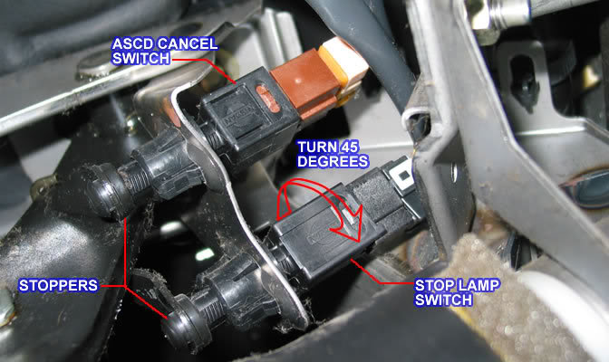
I snapped a pic of the clutch pedel switch for you to look at and make sure it's not missing anything. The clutch pedel DOES close the switch when the clutch is out and it DOES cancel the "cruise" light in the cluster when I step on the clutch so I think the switch is fine and not missing the piece that others say to check.
EDIT: I was just looking back on the things i have already tested with a multi-meter and it looks like i have already tested the brake and clutch pedal switches and they checked out with the proper voltage.

Last edited by 2brosgixxer; 08-16-2013 at 05:47 PM.
08-16-2013, 06:00 PM
#58
No driving needed for EL-164. You are checking the cruise control switches on the steering wheel to see if they are making and breaking the connection. In illustration A it is telling you to unplug the connector from the control module under the dash and check pins 1 and 2 for 12 volts with a certain button pressed. If the voltage measurements are incorrect, the illustration B says to check the continuity of the steering wheel switches on the switches. In both tests, the ignition switch is off.
08-16-2013, 06:10 PM
#59
Senior Member
Thread Starter
Join Date: Oct 2011
Location: Maine
Posts: 1,528
No driving needed for EL-164. You are checking the cruise control switches on the steering wheel to see if they are making and breaking the connection. In illustration A it is telling you to unplug the connector from the control module under the dash and check pins 1 and 2 for 12 volts with a certain button pressed. If the voltage measurements are incorrect, the illustration B says to check the continuity of the steering wheel switches on the switches. In both tests, the ignition switch is off.
08-16-2013, 09:40 PM
#60
You did, but only partially. When I compare my blurb (post 43) to the troubleshooting section in the FSM, I only told you to check for 12 volts on the pins, while the manual says to check for both 12 volts when the button is pressed and zero volts when the button is released. They want to make sure that a switch isn't shorted in the closed (button pressed) position.
And the FSM also asks you to check the CANCEL switch, which I ignored/overlooked.
Pin 1 is the RESUME switch, pin 2 is the SET switch.
The CANCEL switch puts 12 volts on both pins 1 and 2 at the same time.
I would like you to do the FSM test. I expect it will probably test good, but it isn't too hard to do and it is more thorough.
The photo of the clutch pedal switch looks good physically. You checked it electrically when you metered pin 5 (post 43).
Last edited by DennisMik; 08-16-2013 at 09:47 PM.
08-16-2013, 10:20 PM
#61
Senior Member
Thread Starter
Join Date: Oct 2011
Location: Maine
Posts: 1,528
I'll try to get around to more thoroughly checking the steering wheel switches this weekend. I also just looked at the brake Pedal switches and they look exactly like the clutch switch as far as the plunger thing goes. The plunger seems like it pushes fully in when the brakes are not applied. I looked at some other pics of peoples brake switches and theirs appear to have a larger rubber stopper on the end though. Doesn't seem like I need those since we tested those switches already and given that they get fully pushed in when I let off the brakes. Just thought it was odd that mine look like they do and others look different. Here's a pic of someone else's I found...you can see the difference as mine do not have that large rubber stopper
So for this, do I need to hook the (+) lead of the meter up to #1 and #2 at the same time?? Just run a jumper wire between the two of them?
So for this, do I need to hook the (+) lead of the meter up to #1 and #2 at the same time?? Just run a jumper wire between the two of them?
Last edited by 2brosgixxer; 08-17-2013 at 01:09 AM.
08-17-2013, 04:59 AM
#62
Senior Member
Thread Starter
Join Date: Oct 2011
Location: Maine
Posts: 1,528
You did, but only partially. When I compare my blurb (post 43) to the troubleshooting section in the FSM, I only told you to check for 12 volts on the pins, while the manual says to check for both 12 volts when the button is pressed and zero volts when the button is released. They want to make sure that a switch isn't shorted in the closed (button pressed) position.
And the FSM also asks you to check the CANCEL switch, which I ignored/overlooked.
Pin 1 is the RESUME switch, pin 2 is the SET switch.
The CANCEL switch puts 12 volts on both pins 1 and 2 at the same time.
I would like you to do the FSM test. I expect it will probably test good, but it isn't too hard to do and it is more thorough.
The photo of the clutch pedal switch looks good physically You checked it electrically when you metered pin 5 (post
43).
08-17-2013, 11:59 AM
#63
Whenever you measure ohms, do not have the power on. If you did this on a circuit with a high current flow, you will damage the meter. In this case, I doubt that you hurt the meter.
You should be able to check the pump motor and the 2 solenoid valves through the unplugged ASCD control box connector. Pin 8 is common to the 3 things (connected to all of them) so one lead from your meter connects here and stays for the 3 measurements.
Pin 8 - common - blue/white stripe = pin 1 on the motor
Pin 9 - motor - white/red stripe = pin 4 on the motor
Pin 10 - air valve solenoid - blue/yellow stripe = pin 2 on the motor
Pin 14 - release valve solenoid - blue/ red stripe = pin 3 on the motor
Way back you did jumper 12 volts to the pump motor (pins 1 & 4) and it ran, so I have to think that for ohms testing, you were either not making connection with the contacts or you had the meter on too low of a scale. Give the wire harness thing a try.
08-20-2013, 09:42 PM
#64
Senior Member
Thread Starter
Join Date: Oct 2011
Location: Maine
Posts: 1,528
OK, I'll give the wire harness a try.
I also asked the mechanic about it the other day and he printed me off this long trouble shooting thing from "Mitchell" something. Anyway, it had something in there about turn the key to "ON" and turn the main cruise switch on, then hold the brake for 5 seconds and if the light blinks xyz. In other words, it shows some different step by step trouble shooting procedures which I'm going to try. He was baffled too as to why the cruise does not work. I almost wonder if the actuator is shot and maybe just not creating the vacuum necessary to control the cruise system
I also asked the mechanic about it the other day and he printed me off this long trouble shooting thing from "Mitchell" something. Anyway, it had something in there about turn the key to "ON" and turn the main cruise switch on, then hold the brake for 5 seconds and if the light blinks xyz. In other words, it shows some different step by step trouble shooting procedures which I'm going to try. He was baffled too as to why the cruise does not work. I almost wonder if the actuator is shot and maybe just not creating the vacuum necessary to control the cruise system
08-20-2013, 10:20 PM
#65
you may need to get some electrical test clips and some pins to be able to be able to probe the wire harness connections for either the ohms or voltages. I posted a photo of mine in post 30. This would let you check the various pins while driving as you don't have to be holding on to the meter probes or anything. This is how I was able to get the voltages I wrote up in post 48.
As for the pump motor, that is going to be hard to tell if it is actually creating vacuum. You know the motor spins because you jumpered it with 12 volts. We don't know a) is the control module telling it to run; b) do the 2 vacuum valve solenoids have good resistance and c) are the vacuum solenoids being told to open and close.
Since you have the Mitchell Motor Repair test, it sure won't hurt anything to try it.
08-20-2013, 11:27 PM
#66
Senior Member
Thread Starter
Join Date: Oct 2011
Location: Maine
Posts: 1,528
Well, I was going to try the harness test tonight...but i started with looking at my brakes cause they are only grabbing half the rotor in the rear. Ran into a big problem  ...New thread on that issue with pics to come. FML
...New thread on that issue with pics to come. FML
Last edited by 2brosgixxer; 08-21-2013 at 01:40 AM.

Thread
Thread Starter
Forum
Replies
Last Post
trasmadean
6th Generation Maxima (2004-2008)
13
02-01-2017 08:20 PM
carlosvq30
5th Generation Maxima (2000-2003)
0
08-17-2015 11:32 AM