anyone have a ks wire diagram for cali motor?
 03-15-2012, 06:36 PM
#1
Member
Thread Starter

Join Date: Feb 2012
Location: MAGNOLIA TX
Posts: 129
anyone have a ks wire diagram for cali motor?
installed a resistor in my knock sensor harness to try to get it through inspection. the resistor didn't work. upon further inspection found that the previous owner at one point tried to bypass the harness by looping the wires. not sure how the wires are actually supposed to run. also found what looks like a repair or possibly the wire that goes there but just not sure since it runs through the harness on both sides of the apparent repair. really trying to solve this problem myself and not have to pay the dealer. I know this is gonna be a difficult issue seeings how it's a california based care but hopefully someone can shed some light on this for me. thanks.
tried uploading a pic of the pc but not letting me do that for some reason or just not doing it the right way

tried uploading a pic of the pc but not letting me do that for some reason or just not doing it the right way
Last edited by ADROX; 03-15-2012 at 06:45 PM.
 03-16-2012, 03:48 AM
#2
Senior Member

Join Date: Oct 2011
Location: Maine
Posts: 1,528
To upload a pic, you need an account like Photobucket. Upload the pic there, copy the direct link url. Then come here and find the little attach photo icon above where you type for your posts then paste that direct link from Photobucket.
03-16-2012, 08:10 AM
#4
Senior Member

Join Date: Nov 2010
Location: Powder Springs, GA
Posts: 400
I have had excellent luck finding wiring diagrams on this site.
Auto - Online Repair Info
http://search.ebscohost.com/
ID: rrcc
PW: rebsco
Select: Auto Repair Reference Center
Fill in: Find Your Vehicle
Follow prompts down to Wiring Diagrams.
Auto - Online Repair Info
http://search.ebscohost.com/
ID: rrcc
PW: rebsco
Select: Auto Repair Reference Center
Fill in: Find Your Vehicle
Follow prompts down to Wiring Diagrams.
 03-16-2012, 09:10 AM
#6
Member
Thread Starter
Join Date: Feb 2012
Location: MAGNOLIA TX
Posts: 129
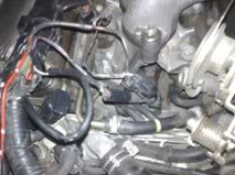
yeah there's a single wire coming out of the main harness and that has a wire that appears to be spliced into it. those both go to the two prong connector that then runs down to the knock sensor.
Last edited by ADROX; 03-16-2012 at 09:37 AM.
03-16-2012, 09:19 AM
#7
Heres how I did mine.
http://forums.maxima.org/4th-generat...tall-pics.html
The resistor doent replace just the sensor, it goes into the connector mounted to the intake manifold and replaces the sensor AND the sub-harness.
http://forums.maxima.org/4th-generat...tall-pics.html
The resistor doent replace just the sensor, it goes into the connector mounted to the intake manifold and replaces the sensor AND the sub-harness.
03-16-2012, 09:45 AM
#8
Member
Thread Starter
Join Date: Feb 2012
Location: MAGNOLIA TX
Posts: 129
the area where the splice is is before the subharness. basically in between the end where you installed the resistor and the main wiring harness is where the apparent splice is. looking at your pics I think you are talking about the ks end as far as there being a single wire. still trying to upload the pics through photobucket but not working for me.
03-16-2012, 09:48 AM
#9
Member
Thread Starter
Join Date: Feb 2012
Location: MAGNOLIA TX
Posts: 129
Last edited by ADROX; 03-16-2012 at 09:54 AM.
 03-16-2012, 10:33 AM
#12
Member
Thread Starter
Join Date: Feb 2012
Location: MAGNOLIA TX
Posts: 129
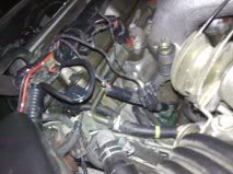
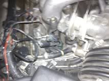
ok so now that it took me an hour to get that up lol. anyway can you see what I'm talking about? that plugs into the sub harness. there is an apparent repair there next to it but don't think that has anything to do with it. also shouldn't there be power to that connection if the key is on even if the motor is not running. tried using an ohm meter and got nothing. the taped of connector is the beginning of the sub harness that runs to the ks.
Last edited by ADROX; 03-16-2012 at 10:42 AM.
03-16-2012, 11:46 AM
#13
Your pictures are to grainy and small.
There should be electrical tape two inches from each end, inside the plastic loom of the subharness pictured below. Ive read before that the main wiring harness is the same construction, with one wire connecting to a shield, and taped.I dont think there will be a voltage present, the KS generates its own voltage and the ECM measures that. You need to down- load the FSM for testing procedures.
To install a resistor, you unplug the left end of the sub harness (in the image below) from the main harness, and plug the resistor into the main harness plug. The resistor needs to be 470K ohm
 </P>
</P>
There should be electrical tape two inches from each end, inside the plastic loom of the subharness pictured below. Ive read before that the main wiring harness is the same construction, with one wire connecting to a shield, and taped.I dont think there will be a voltage present, the KS generates its own voltage and the ECM measures that. You need to down- load the FSM for testing procedures.
To install a resistor, you unplug the left end of the sub harness (in the image below) from the main harness, and plug the resistor into the main harness plug. The resistor needs to be 470K ohm
</P>
Last edited by asand1; 03-16-2012 at 11:48 AM.
03-16-2012, 11:53 AM
#14
Down load the FSM here.
http://www.nicoclub.com/FSM/maxima/
http://www.nicoclub.com/FSM/maxima/
03-16-2012, 02:07 PM
#15
Member
Thread Starter
Join Date: Feb 2012
Location: MAGNOLIA TX
Posts: 129
yeah I stuck it in the connection that you are saying, which is the end that is hanging there that I am questioning the 'splice', with a 470k ohm resistor as I had read in the forums and reset the ecu under the dash but it still set off the code again when the 0111 popped back up. that's why I was thinking the wire that looks as though it's spliced was someone trying to loop or bypass the sensor. would have thought the resistor would have kept the 0304 code off all together if it was in there.
03-16-2012, 02:26 PM
#17
Member
Thread Starter
Join Date: Feb 2012
Location: MAGNOLIA TX
Posts: 129
had the 0102 maf code and 0210 fuel injection system left bank lean awhile back but got them cleared by cleaning the maf and replacing the front o2 sensor. ks stayed as a ghost code after the system was done testing and a week later the 0111 came up of course along with the 0304 ks but that's it.

Thread
Thread Starter
Forum
Replies
Last Post
QueensMAX
5th Generation Maxima (2000-2003)
7
09-15-2015 04:14 AM
popdedop
7th Generation Maxima (2009-2015)
6
09-11-2015 11:17 AM