A little help on FI sub harness wiring?!?
 11-12-2014, 09:42 AM
#1
Junior Member
Thread Starter

Join Date: Sep 2014
Location: Lake Goodwin, WA and Honolulu, HI
Posts: 78
A little help on FI sub harness wiring?!?
Hello guys, I figured if I got a few pictures on maybe I'll get some help. I have no pulse power going to the 2,4 and 6 injectors on this Gen3 1991 Maxima. Ive heard it never had much power before the timing belt blew and this is probably the culprit. I replaced the engine and installed new timing belt on the replacement. Looking at this set-up and it doesn't jive with the wiring diagram but being "Not a mechanic" I thought maybe you guys who know these cars might be able to help. Here is the harness that comes out of the Main Wiring Harness: 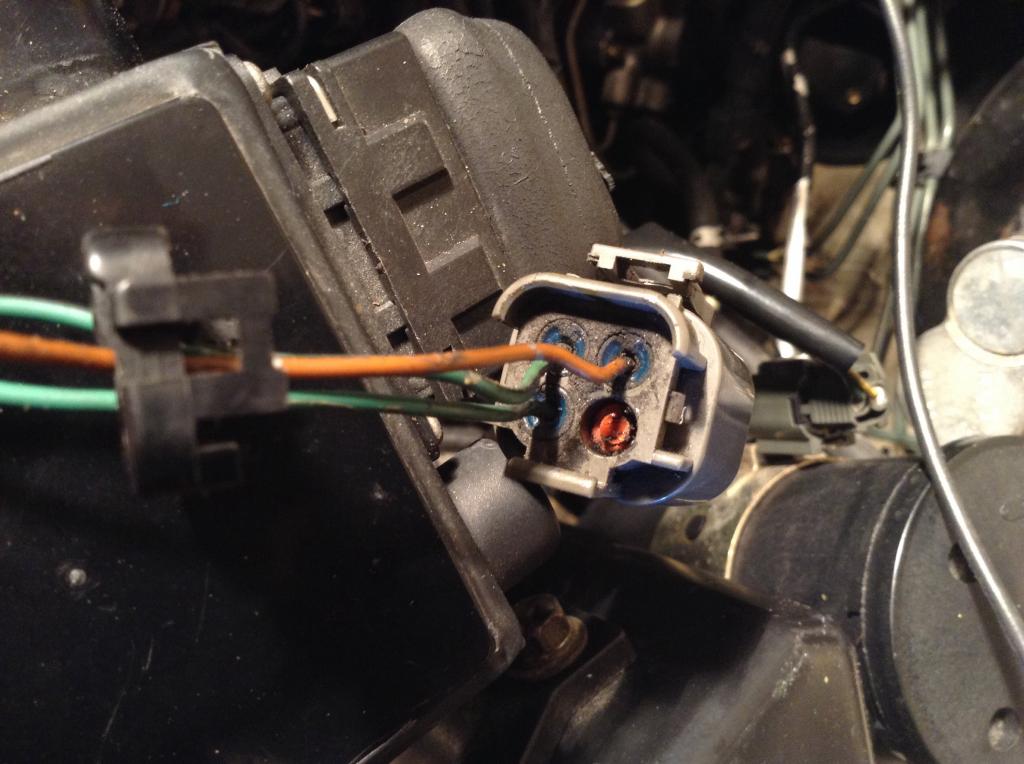
It, as you can see, has only 3 wires. A red plug in # 4 which, if my deductions are correct, is supposed to feed injector #6.
1 of the pins has constant 12v current when the key is on and heads up into the main harness. Another one splices into the AAC harness here:
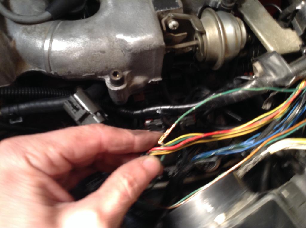
Coming out of the main harness in the same group as the 2 other FI wires is this wire that splices into the transmission harness wiring with the same small brass crimp splice.
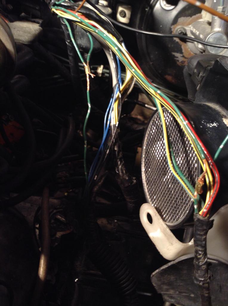
It splices into the harness that feeds this jacketed AT wire harness.
So, it looks pretty weird. A couple questions come to my "not a mechanic" mind.
1) should the plug on the main harness side have 4 wires going into it? In my mind...reading the wiring diagram, there should be 1 for each injector for the pulse signal and 1 for the power.
2) dumb question probably but...did Nissan ever splice like this or is this another backyard mechanic like me. . Doing his best to make it work?
3) where do I go from here to get the power to the injectors in the right firing order?
4) because I have only 14 posts is anyone even going to reply.
Any help would be greatly appreciated!!!!!
It, as you can see, has only 3 wires. A red plug in # 4 which, if my deductions are correct, is supposed to feed injector #6.
1 of the pins has constant 12v current when the key is on and heads up into the main harness. Another one splices into the AAC harness here:
Coming out of the main harness in the same group as the 2 other FI wires is this wire that splices into the transmission harness wiring with the same small brass crimp splice.
It splices into the harness that feeds this jacketed AT wire harness.
So, it looks pretty weird. A couple questions come to my "not a mechanic" mind.
1) should the plug on the main harness side have 4 wires going into it? In my mind...reading the wiring diagram, there should be 1 for each injector for the pulse signal and 1 for the power.
2) dumb question probably but...did Nissan ever splice like this or is this another backyard mechanic like me.
. Doing his best to make it work? 3) where do I go from here to get the power to the injectors in the right firing order?
4) because I have only 14 posts is anyone even going to reply.
Any help would be greatly appreciated!!!!!
 11-14-2014, 10:08 AM
#2

Did you ever check the resistance of the fuel injector coils? As someone else said, they should measure around 12 ohms. As the resistance reading gets higher, the injector will still work, but the the valve doesn't open fully. The higher the resistance, the less fuel. I had fuel injectors the measured around 75 ohms that still sort of worked, but barely. By the time an injector gets into the 20 ohm range, you should get ready to replace it.
There are 3 wires going to each fuel injector, 12 volts, ground and trigger signal. The 12 volt wire and ground wires should be the same color at every injector. The trigger wire will be a different color at each injector. The trigger wires (you call it the pulse wire) go to the ECU that connects the wire to ground to make the injector work.
Besides checking the ohm readings (done with the wire harness unplugged), check that each injector is getting 12 volts. Also check the ground wire. With the power off, check wire continuity to ground. It should be zero ohms.
Then comes the fun part. Since you don't have the trigger signal, unplug the wire harness from the ecu and measure the wire continuity between the fuel injector plug and the ECU plug. If you don't have continuity, then I would suggest you work your way from the fuel injector plug, checking continuity towards the ECU. Since each injector has it's own wire, I would hope that you can find a common point for all 3 wires. When you get to the spots in the wire harness that are cut open, be watching the wire colors. I hope these are not the splices you have noted.
Injector 2 --> ECU pin 110
Injector 4 --> ECU pin 112
Injector 6 --> ECU pin 114
Injector 1 --> ECU pin 101
Injector 3 --> ECU pin 103
Injector 5 --> ECU pin 105
In your photos, MOST of the time (but not always) a green wire is a ground wire. Black wires go directly to ground, green wires go through a switch. Those splices may not really be a problem, but I can't be certain.
11-14-2014, 11:57 AM
#3
Junior Member
Thread Starter
Join Date: Sep 2014
Location: Lake Goodwin, WA and Honolulu, HI
Posts: 78
Did you ever check the resistance of the fuel injector coils? As someone else said, they should measure around 12 ohms. As the resistance reading gets higher, the injector will still work, but the the valve doesn't open fully. The higher the resistance, the less fuel. I had fuel injectors the measured around 75 ohms that still sort of worked, but barely. By the time an injector gets into the 20 ohm range, you should get ready to replace it.
There are 3 wires going to each fuel injector, 12 volts, ground and trigger signal. The 12 volt wire and ground wires should be the same color at every injector. The trigger wire will be a different color at each injector. The trigger wires (you call it the pulse wire) go to the ECU that connects the wire to ground to make the injector work.
Besides checking the ohm readings (done with the wire harness unplugged), check that each injector is getting 12 volts. Also check the ground wire. With the power off, check wire continuity to ground. It should be zero ohms.
Then comes the fun part. Since you don't have the trigger signal, unplug the wire harness from the ecu and measure the wire continuity between the fuel injector plug and the ECU plug. If you don't have continuity, then I would suggest you work your way from the fuel injector plug, checking continuity towards the ECU. Since each injector has it's own wire, I would hope that you can find a common point for all 3 wires. When you get to the spots in the wire harness that are cut open, be watching the wire colors. I hope these are not the splices you have noted.
Injector 2 --> ECU pin 110
Injector 4 --> ECU pin 112
Injector 6 --> ECU pin 114
Injector 1 --> ECU pin 101
Injector 3 --> ECU pin 103
Injector 5 --> ECU pin 105
In your photos, MOST of the time (but not always) a green wire is a ground wire. Black wires go directly to ground, green wires go through a switch. Those splices may not really be a problem, but I can't be certain.
There are 3 wires going to each fuel injector, 12 volts, ground and trigger signal. The 12 volt wire and ground wires should be the same color at every injector. The trigger wire will be a different color at each injector. The trigger wires (you call it the pulse wire) go to the ECU that connects the wire to ground to make the injector work.
Besides checking the ohm readings (done with the wire harness unplugged), check that each injector is getting 12 volts. Also check the ground wire. With the power off, check wire continuity to ground. It should be zero ohms.
Then comes the fun part. Since you don't have the trigger signal, unplug the wire harness from the ecu and measure the wire continuity between the fuel injector plug and the ECU plug. If you don't have continuity, then I would suggest you work your way from the fuel injector plug, checking continuity towards the ECU. Since each injector has it's own wire, I would hope that you can find a common point for all 3 wires. When you get to the spots in the wire harness that are cut open, be watching the wire colors. I hope these are not the splices you have noted.
Injector 2 --> ECU pin 110
Injector 4 --> ECU pin 112
Injector 6 --> ECU pin 114
Injector 1 --> ECU pin 101
Injector 3 --> ECU pin 103
Injector 5 --> ECU pin 105
In your photos, MOST of the time (but not always) a green wire is a ground wire. Black wires go directly to ground, green wires go through a switch. Those splices may not really be a problem, but I can't be certain.
Thanks Dennis! I got it figured out! I had ohm'd the injectors while I was swapping motors. I finally found a 1991 FSM and found the info on pins and wire colors as well. I went back to the wiring harness and looked for the color coded wires that were supposed to feed the FI sub harness and found them....traced them down to....low and behold....another 4 pin plug that I had mistakenly plugged into another female. Swapped them out and all is well!!! A little embarrassing but live and learn.
. Thanks for the reply!!!!!!
11-14-2014, 04:38 PM
#4
Junior Member
Thread Starter
Join Date: Sep 2014
Location: Lake Goodwin, WA and Honolulu, HI
Posts: 78
Almost there!!!
The car runs great. I do still get the engine light and code 51 ( Fuel Injection) but only when I touch the gas peddle. Weird. I adjust the idle screw too per the FSM and I can't get it below 1100 rpm even with bottoming the screw out. I'll keep troubleshooting though. It's been a good pastime during this cancer crap!! I'm used to being on job sites with hundreds of people looking to me for answers...my last job had thousands of workers....built the Disney Aulani Resort as a Manager of the project my phone would go off over 200 times a day with calls and emails....this sitting around the house isn't my style!!! The car has been a great distraction. Thanks for the help guys! 
11-14-2014, 06:25 PM
#5

It looks like you have an automatic. Make sure you don't mix the connector that goes to the pnp (inhibitor) switch with the fuel injector connector. The pnp color has 3 wires on the connector while the injector connector should have four.
I recently swapped the engine harness on my car and did the same mistake when it was misfiring and the iacv would not fully close, even though I was fully aware of the issue.
EDIT: oops looks like you took care of that on your next post. But yea, I don't know why Nissan didn't bother to use a different plug for the trans, but I plan to take care of that soon, hopefully.
But looks like your idle won't go down either. Make sure you swap the connector for that too!
Last edited by jbbons25; 11-14-2014 at 06:50 PM.
11-14-2014, 06:58 PM
#6

Those simple crush splices are actually fairly common and usually buried deep within wire looms on factory wire harness. I've always wondered why they're not soldered or anything but I've found them on my Maximas and my Civics over the years and Nissan and Honda both know what they're doing so I assume all is copacetic with them.
11-14-2014, 07:58 PM
#7

They used crimped splicing because soldered joints supposibly corrode over the years if the soldering process is contaminated. I usually o around resoldering all the crimped in splices with the newer resin intergrated solder. I upgraded to the later model 93-94 FI setup...
11-15-2014, 10:14 AM
#8
Junior Member
Thread Starter
Join Date: Sep 2014
Location: Lake Goodwin, WA and Honolulu, HI
Posts: 78
Those simple crush splices are actually fairly common and usually buried deep within wire looms on factory wire harness. I've always wondered why they're not soldered or anything but I've found them on my Maximas and my Civics over the years and Nissan and Honda both know what they're doing so I assume all is copacetic with them.
Thanks James and cMax! Digging in a little deeper I've found more of them too. One in the sub harness as well.
11-15-2014, 10:18 AM
#9
Junior Member
Thread Starter
Join Date: Sep 2014
Location: Lake Goodwin, WA and Honolulu, HI
Posts: 78
It looks like you have an automatic. Make sure you don't mix the connector that goes to the pnp (inhibitor) switch with the fuel injector connector. The pnp color has 3 wires on the connector while the injector connector should have four.
I recently swapped the engine harness on my car and did the same mistake when it was misfiring and the iacv would not fully close, even though I was fully aware of the issue.
EDIT: oops looks like you took care of that on your next post. But yea, I don't know why Nissan didn't bother to use a different plug for the trans, but I plan to take care of that soon, hopefully.
But looks like your idle won't go down either. Make sure you swap the connector for that too!
I recently swapped the engine harness on my car and did the same mistake when it was misfiring and the iacv would not fully close, even though I was fully aware of the issue.
EDIT: oops looks like you took care of that on your next post. But yea, I don't know why Nissan didn't bother to use a different plug for the trans, but I plan to take care of that soon, hopefully.
But looks like your idle won't go down either. Make sure you swap the connector for that too!

More investigation I guess.
EDIT: Oh, and I did swap both the plugs that were incorrect. :-)
Last edited by Not a mechanic!; 11-15-2014 at 10:21 AM.

Thread
Thread Starter
Forum
Replies
Last Post
Kyle Lee Cleveland
6th Generation Maxima (2004-2008)
3
09-28-2015 07:58 AM