CHECK ENGINE LIGHT Diagnosis (If "trouble" lights are on, read here first!)
 03-12-2002, 05:35 PM
#1
CHECK ENGINE LIGHT Diagnosis (If "trouble" lights are on, read here first!)
Use this IF YOU HAVE A CHECK ENGINE LIGHT!!!!!!!!!!!
How to get the code:
http://vbxmaxima.8m.com/ecu.html
What the code means:
http://vbxmaxima.8m.com/ecudecoder.html
Be very gentle with this screw, do not push it in too hard. It is very delicate and can break off with very little effort.
If you broke the screw off, you can buy a cheap code reader on ebay. I got mine for less than $30. It is lot easier to check and reset the code. Plug it in right near the fuse panel, read the code and then let it reset them.
Got fed up with people *****ing about undefined codes in the existing 'decoder', so over the last few days I made this:
pmohr's A32 CEL Decoder
It's got every code from each year's respective FSM, including any AT faults that set a P or MIL code. Most of the emissions (and most notably, the O2 codes) are year specific, so be sure to select the correct year at the top.
If it comes up saying 'code not found', then either you typed in the wrong code number (typo or misread from the CEL), or it's possible, though very unlikely that the code exists but is not listed in the FSM.
In the 'Code' input, either enter the 4 digit code you get from the flashing CEL (0304 for KS, 0701 for Multiple Cylinder Misfire, etc).
You can also enter OBD-II P-codes (P0325 for KS, P0300 for Multiple Cylinder Misfire, etc) but be sure you include the P.
If you enter some OBD-II codes without the P, you'll get incorrect results. For example, 0505 means nothing is wrong, but P0505 is an IACV fault.
You can link to each individual search result, either through the address bar in your browser or via the 'Link to this page' link at the bottom of the results.
For example, knock sensor code for a '96, or swirl control valve for a '99.
I encourage as many people as possible to give it a try, by all means PM me if you find any typos, incorrect information, etc. I want to make this thing perfect so we have no more 'undefined code' posts.
Last edited by Kevlo911; 06-29-2009 at 11:51 AM.
 08-02-2002, 08:13 AM
#2
Supporting Maxima.org Member

Join Date: Oct 2000
Posts: 9,159
My OD light is blinking, what does that mean?
AT diagnostic
__________________________________________________ ________________
95-97
1. Start engine and warm to normal operating temp with O/D off.
2. Turn ignition swith to off postiton wait 5 sec.
3. Turn ignition switch to the ACC position.
4. Put O/D to ON.
5. Move shifter to P, turn ignition on but don't start engine.
6. The OD light should come on for about 2 secs.
a. if light does not come on somthing is wrong with the trans. computer.
b. if light comes on proceed to no 7.
7. Turn ignigton key to off.
8. Turn ignition key to on, don't start engnie.
9. Move shift lever to D, trun ignition to off.
10. Put O/D switch to off position.
11. Turn ignition off.
12. Put O/D to off, turn ignition ON wait 2sec and move shifter to the 2 position.
13. Put O/D to on, move shifter to 1 position.
14. Put O/D to off, depress accelerator all the way to floor and release.
15. The computer is now in output mode and will start displaying the codes.
There�s one long flash that signifies the start of the sequence. Following
should be 10 short flashes. Then it
repeats.
Remember the first long flash indcates the start of the sequence followed by
10.
All 10 flashes the same = No error codes read at this time
1st flash longer than others = Revolution sensor is shorted or disconnected.
2nd flash longer than others = Speed sensor circuit is shorted or disconnected.
3rd flash longer than others = Throttle sensor circuit is shorted or
disconnected.
4th flash longer than others = Shift solenoid �A� circuit is shorted or
disconnected
5th flash longer than others = Shift solenoid �B� circuit is shorted or
disconnected
6th flash longer than others = Overrun clutch solenoid circuit is shorted or
disconnected
7th flash longer than others = Lock-up solenoid circuit is shorted or
disconnected
8th flash longer than others = Fluid temperature sensor is disconnected or A/T
control unit power source
circuit is damaged.
9th flash longer than others = Engine revolution signal circuit is shorted or
disconnected
10th flash longer than others = Line pressure solenoid circuit is shorted or
disconnected
All the same with no long start flash = Battery low, been disconnected, or
control unit has just been
reconnected.
OMG! My overdrive light is blinking!
This Transmission Control Module self-diagnostic procedure information was abstracted from the '99 Maxima factory service manual. It applies to '98 and '99 models. Plain Jane (my '99 GXE) is a 5-speed so this procedure has not been personally tested.
1) Move the shift selector to Park.
Start the engine and let it run until it reaches normal operating temperature.
2) Turn the ignition switch OFF.
3) Wait at least five seconds.
4) Turn the ignition switch ON but do not start the engine.
5) The O/D OFF indicator lamp should turn on for about two seconds.
If it does not, stop here because the rest of this procedure won't work.
6) Turn the ignition switch OFF.
7) Turn the ignition switch to ACC.
8) Move the shift selector from Park to Drive.
9) Turn the ignition switch ON but do not start the engine.
10) Press and hold the O/D OFF button.
Continue to press the O/D OFF button until step 13 (below).
The O/D OFF indicator lamp should be on.
If not, stop here because the rest of this procedure won't work.
11) Turn the ignition switch OFF.
12) Turn the ignition switch ON but do not start the engine.
13) Release the OD/OFF button.
The O/D OFF indicator lamp will be off.
14) Wait two seconds.
15) Move the shift selector from Drive to 2.
16) Press and release the O/D OFF button.
The O/D OFF indicator lamp will be on.
17) Press and hold the O/D OFF button.
Continue to press the O/D OFF button until step 19 (below).
The O/D OFF indicator lamp should be off.
18) Move the shift selector from 2 to 1.
19) Release the OD/OFF button.
20) Press and release the O/D OFF button.
The O/D OFF indicator lamp will be on.
21) Press and release the O/D OFF button.
The O/D OFF indicator lamp will be off.
22) Press and hold the O/D OFF button.
Continue to press the O/D OFF button until step 24 (below).
The O/D OFF indicator lamp should be on.
23) Press the gas pedal to the floor and then release it.
24) Release the OD/OFF button.
25) The O/D OFF indicator lamp will exhibit a sequence of flashes.
The first flash is distinctly longer than the others.
Subsequent flashes are very short and these are called Judgement
Flickers.
Count those JFs and watch for one which is twice as long as the others.
Interpreting Judgement Flickers...
JF0) All JFs are short.
All circuits which can be confirmed by this self-diagnosis procedure are okay.
JF1) The 1st JF is longer than the others.
The Revolution Sensor is short-circuited or disconnected.
JF2) The 2nd JF is longer than the others.
The Vehicle Speed Sensor is short-circuited or disconnected.
JF3) The 3rd JF is longer than the others.
The Throttle Position Sensor is short-circuited or disconnected.
JF4) The 4th JF is longer than the others.
The Shift Solenoid A circuit is short-circuited or disconnected.
JF5) The 5th JF is longer than the others.
The Shift Solenoid B circuit is short-circuited or disconnected.
JF6) The 6th JF is longer than the others.
The Overrun Clutch Solenoid Valve circuit is short-circuited or disconnected.
JF7) The 7th JF is longer than the others.
The Torque Converter Solenoid Valve circuit is short-circuited or disconnected.
JF8) The 8th JF is longer than the others.
The ATF Temperature Sensor is disconnected or the TCM power source circuit is damaged.
JF9) The 9th JF is longer than the others.
The Engine Speed circuit is short-circuited or disconnected.
JF10) The 10th JF is longer than the others.
The Line Pressure Solenoid Valve circuit is short-circuited or disconnected.
If the O/D OFF indicator lamp exhibits a series of long flashes, these
are not Judgement Flickers.
This condition indicates a problem with the battery.
The battery may ...
- be discharged
- have been disconnected for a long time
- be connected with reversed polarity
If the O/D OFF indicator lamp stays on continuously, this is not a Judgement Flicker. This condition indicates any of these conditions ...
- PNP switch is disconnected
- O/D OFF button circuit is damaged
- Throttle Position Sensor circuit is disconnected
- Transmission Control Unit is damaged
I would be worried about your tranny...be ready for a big repair.
Last edited by phenryiv1; 01-11-2008 at 11:58 AM.
07-25-2003, 09:59 AM
#3
DBM ECU CODES
(All May or May not be Definded By Daniel B. Martin)
0101
My book says DTC 0101 is caused by the Camshaft Position Sensor (Phase). This sensor is located on the engine front cover facing the camshaft sprocket. It detects the cylinder number signal. The Engine Control Module uses this signal to control spark plug firing order and also to sequence the fuel injectors correctly. If the CPS is bad the ECM will fire the plugs at the wrong time, or not fire them at all. This would account for a no-fire symptom.
0102
Diagnostic Trouble Code 0102 points to a problem with the Mass Air Flow Sensor. The MAFS is placed in the stream of intake air. It measures the intake flow rate by measuring a part of the entire intake flow. It consists of a thin film that is supplied with electric current from the Engine Control Module. The temperature of the hot film is controlled by the ECM a certain amount. The heat generated by the hot wire is reduced as the intake air flows around it. The more air, the greater the heat loss. Therefore, the ECM must supply more electric current to the hot film as air flow increases. This maintains the temperature of the hot film. The ECM detects the air flow by means of this current change.
This malfunction is detected when an out-of-range voltage is sent to the ECM. That voltage might be too high or too low.
a) An excessively high voltage from the MAFS is sent when the engine is not running.
b) An excessively high voltage from the MAFS is sent under light load driving conditions.
Possible causes include...
- Harness or connectors (the sensor circuit is open or shorted.)
- Faulty MAFS
c) An excessively low voltage from the MAFS is sent when the engine is not running.
d) An excessively low voltage from the MAFS is sent under heavy load driving conditions.
Possible causes include...
- Harness or connectors (the sensor circuit is open or shorted.)
- Intake air leaks
- Faulty MAFS
With DTC 0102 the ECM is supposed to switch into Fail Safe mode and limit engine speed to 2400 rpm.
0103
OBD-2 Diagnostic Trouble Codes are always four digits. Your DTC "13" is actually "0103", and it points to the Engine Coolant Temperature Sensor. The factory service manual says this DTC is set when the ECTS signal has an excessively high or low voltage. It suggests testing the ECTS and also the associated electric connector and wiring harness.
On the 4th Generation Maxima engine the Engine Coolant Temperature Sensor is located in the water outlet tube close to the engine end of the upper radiator hose. There are two sensors in that area. The one nearest the hose is for the dashboard temperature gauge. The ECTS, the one you're interested in, is right next to the the gauge sending unit. There is a good picture of these sensors in the Haynes manual on page 3-7.
With the engine cold, disconnect the ECTS and measure its resistance. Reconnect the ECTS, start the engine, run it until fully warmed up. Stop the engine, and repeat the resistance measurement. The "warm" reading should be a much lower value than the "cold" reading.
The specs for the ECTS are:
Engine coolant temperature 68F, ECTS resistance 2.1 - 2.9 Kohms
Engine coolant temperature 194F, ECTS resistance 0.24 - 0.26 Kohms
(Roughly a factor of ten difference.)
0104
Diagnostic Trouble Code 0104 points to a problem with the Vehicle Speed Sensor or the associated wiring.
The Vehicle Speed Sensor installed on the transaxle. The part inside the transaxle has a plastic gear which is driven by the internal parts of the transaxle. The part outside is a signal generator which produces a square wave of amplitude 5.2 volts and frequency proportional to vehicle speed.
Remove the VSS, attach a voltmeter to the electric leads, and spin the gear
by hand. If you get zero volts, it's dead.
One owner discovered his VSS was not fully seated in the transaxle. He just tapped it inward, and retightened the 10mm mounting bolt.
For more information please refer to the Chilton repair manual (page 4-22) or the Haynes repair manual (page 6-16).
0111
Diagnostic Trouble Code 0111 is detected when ...
- EVAP control system does not operate properly.
- EVAP control system has a leak in the line between intake manifold and EVAP control system pressure sensor.
Possible causes include ...
- EVAP canister purge volume control solenoid valve stuck closed.
- EVAP control system pressure sensor and its circuit.
- Loose, disconnected, or improper connection of rubber tube.
- Blocked rubber tube.
- Blocked or bent rubber tube to MAP/BARO switch solenoid valve.
- Cracked EVAP canister.
- EVAP canister purge volume control solenoid valve.
- Closed Throttle Position Switch.
- Improper connection of one-way valve.
- Blocked purge port.
- EVAP canister vent control valve.
This is a "jackpot" code. It points to so many possible causes as to be almost useless. It may be accompanied by another DTC which is more specific.
0114
Diagnostic Trouble Code 0114 indicates a problem with the fuel management system on the right cylinder bank. The right bank is also called the rear bank. It is cylinders 1,3,5.
The Front Heated Oxygen Sensor for the right bank sent signals to the Engine Control Module indicating an excessively rich fuel mixture. The ECM attempted to correct this problem by directing the fuel injectors to supply less gasoline. Further signals from the Oxygen Sensor indicate that the attempt to correct the rich mixture condition was unsuccessful, and the fuel mixture continues to be too rich.
Possible causes include ...
- Intake air leaks
- Defective Front Heated Oxygen Sensor
- Fuel injectors
- Exhaust gas leaks
- Incorrect fuel pressure
- Lack of fuel
- Faulty Mass Air Flow Sensor
Before tackling anything involving DTC 0114, I would bench test the EVAP CVCV first. It probably needs replacement. Then I would reset the ECU and see if the light comes back indicating you are still running rich on the rear cylinder bank. Most likely, the 0114 will be an Oxygen Sensor if replacing the EVAP CVCV didn't resolve everything..
0115
Diagnostic Trouble Code 0115 indicates a problem with the fuel management system on the right cylinder bank. The right bank is also called the rear bank. It is cylinders 1,3,5.
The Front Heated Oxygen Sensor for the right bank sent signals to the Engine Control Module indicating an excessively lean fuel mixture. The ECM attempted to correct this problem by directing the fuel injectors to supply more gasoline. Further signals from the Oxygen Sensor indicate that the attempt to correct the lean mixture condition was unsuccessful, and the fuel mixture continues to be too lean.
Possible causes include ...
- Intake air leaks
- Defective Front Heated Oxygen Sensor
- Fuel injectors
- Exhaust gas leaks
- Incorrect fuel pressure
- Lack of fuel
- Faulty Mass Air Flow Sensor
0201
Diagnostic Trouble Code 0201 indicates a problem with the ignition coil and power transistor. The ignition signal from the Engine Control Module is sent to and amplified by the power transistor. The power transistor turns on and off the ignition coil primary circuit. This on-off operation induces the proper high voltage in the coil secondary circuit.
The malfunction is detected when the ignition signal in the primary circuit is not entered during engine cranking or running.
The items to check include
- Harness or connectors (the ignition primary circuit is open or shorted.)
- Power transistor unit built into ignition coil
- Condenser
- Crankshaft Position Sensor (REF)
- Crankshaft Position Sensor (REF) circuit
A misfire on any individual cylinder should set a code, and a problem with the CPS should also set a code.
I would have expected to see DTC 0201 along with one of the following DTCs.
0407 - Crankshaft Position Sensor (REF)
0608 - Cylinder 1 misfire
0607 - Cylinder 2 misfire
0606 - Cylinder 3 misfire
0605 - Cylinder 4 misfire
0604 - Cylinder 5 misfire
0603 - Cylinder 6 misfire
You didn't get one of these "companion" DTCs, and that is puzzling. Maybe one of them will show up in the next few days.
0203
http://forums.maxima.org/showthread....highlight=0203
0205
http://forums.maxima.org/showthread....highlight=0205
0209
http://forums.maxima.org/showthread....highlight=0209
0210
Diagnostic Trouble Code 0210 points to a problem with the fuel injection system. When the engine management system is running in closed-loop mode the Engine Control Unit (the computer) makes continual adjustments to maintain the air-fuel ratio near the ideal point. To achieve this it relies on signals from many sensors including the Mass Air Flow Sensor and the Oxygen Sensors.
This malfunction is detected when the ECM finds that it cannot properly control the air/fuel mixture, and the mixture is too lean (too much air). DTC 0210 indicates this problem exists on the left bank (the front bank, cylinders 2, 4, and 6). Possible causes include ...
- Intake air leaks
- Front Oxygen Sensor
- one or more fuel injectors on the front bank
- exhaust gas leaks
- incorrect fuel pressure
- lack of fuel
- Mass Air Flow Sensor
0301
ECU
0302
Diagnostic Trouble code 0302 points to a problem with the Exhaust Gas Recirculation system. The malfunction is detected by the Engine Control Module when no EGR flow is detected under conditions which call for EGR. Possible causes include:
- The electrical harness or connectors (valve circuit open or shorted)
- The EGR valve is stuck closed
- Weak or dead battery
- The EGR passage is clogged
- Faulty EGR temperature sensor circuit
- A leak somewhere in the exhaust system
The EGR Volume Control Valve may be tested with an ohmmeter. Disconnect the electrical connector. Looking at the connector half which is attached to the EGRVCV with the latch at the 12 o'clock position you will see two rows of three terminals. The top row is numbered 1-3, right to left. The bottom row is numbered 4-6, right to left. Measure the resistance between these terminal pairs:
2 1
2 3
5 4
5 6
... all resistance values should be 20.9-23.1 ohms at 68 degrees F.
Reconnect the EGRVCV connector halves. Turn the ignition switch ON OFF repeatedly. Verify that the EGRVCV shaft moves smoothly forward backward according to the ignition switch position.
The Exhaust Gas Temperature Sensor may be tested with an ohmmeter. The specifications are ...
- at 32 degrees F, 0.68-1.11 Megohms
- at 122 degrees F, 0.09-0.12 Megohms
- at 212 degrees F, 0.017-0.024 Megohms
0303
Diagnostic Trouble Code 0303 indicates a problem with the front Oxygen Sensor on the left cylinder bank. The left bank is also called the front bank. It is cylinders 2,4,6. A normal signal sweeps back and forth between 0.2 volts and 0.8 volts. This malfunction was detected when the Engine Control Module received a signal from the sensor which was a constant value of approximately 0.3 volts.
Possible causes include ...
- Harness or connectors (the sensor circuit is open or shorted).
- Defective Oxygen Sensor
0304
Diagnostic Trouble Code 0304 points to a problem with the Knock Sensor. The KS is attached to the cylinder block. It senses engine knocking using a piezoelectric element. A knocking vibration from the cylinder block is senses as vibrational pressure. This pressure is converted into a voltage signal and sent to the Engine Control Module (The computer).
This malfunction is detected when an excessively high or low voltage from the KS is entered to the ECM. Possible causes include...
- the harness or connector (The KS circuit is open or shorted).
- the KS
The KS may be checked with an ohmmeter.
1) Raise the hood. View the engine from the driver's fender. Look into
the deep valley between the cylinder banks and below the intake manifold.
Identify the KS as a black item fastened to the block by a single vertical
bolt. A wire harness wrapped in black leads toward you, out of the valley.
That is the KS sub-harness.
2) Follow the KS sub-harness to it's nearest connector. This is connector F121.
It is located near the upper right-hand corner of the valve cover of the forward cylinder bank, as viewed from the front of the car.
3) Disconnect F121. You have to do a "press the latch and wiggle and
pull" to disconnect it. F121 has only two pins; if you see more than two
pins, you have the wrong connector. Use a digital ohmmeter capable of
measuring more than 10 Megohms. You want to measure the pins of F121, not
the sockets of the matching connector. Measure the resistance between a
good ground (such as the battery negative terminal) and pin #2 of connector
F121. On my car this is the highest of the two pins, the one closest to
the front of the car. The factory spec is 500 - 620 Kohms.
The manual says you have to remove the intake manifold to replace the KS. However, I think that a person with good dexterity and a 12mm ratcheting box wrench could replace the KS without disturbing the manifold.
Important note: the dealer can do a more thorough test with his CONSULT electronic tester. The resistance test described here is a useful but limited test. A Knock Sensor which fails this test is definitely bad. However, a KS which passes this test is not guaranteed to be good.
0305
Diagnostic Trouble Code 0305 points to a problem with the Exhaust Gas Recirculation Temperature Sensor. This sensor is a thermistor (a resistor with a value which varies inversely with temperature). The EGRTS is used by the Engine Control Module to test the EGR system operation. Since the signal from the EGRTS is not used for engine operation your car should run perfectly well despite having the Check Engine Light on.
Possible causes of DTC 0305 include ...
- harness or connectors (The EGRTS circuit is open or shorted)
- bad EGRTS
- malfunction elsewhere in the EGR system
The EGRTS may be tested with an ohmmeter.
- at "D" degrees F the resistance should "R" (in Megohms) should be ...
D = 32, R = 0.68-1.11
D = 122, R = 0.09-0.12
D = 212, R = 0.017-0.024
0306
http://forums.maxima.org/showthread....highlight=0307
0307
Diagnostic Trouble Code 0307 points to a problem with the Engine Control Module Closed Loop Logic for the Left Bank. The left cylinder bank is also called the front bank. It is cylinders 2,4,6.
DTC 0307 is detected when the closed loop control function for the left bank does not operate even when the vehicle conditions meet the criteria (engine at normal operating temperature, etc.). Possible causes include ...
- Harness or connectors (The sensor circuit is open or shorted.)
- a defective Front Heated Oxygen Sensor sensing element.
- a defective Front Heated Oxygen Sensor heater.
0308
Diagnostic Trouble Code 0308 points to a problem with the Engine Control Module Closed Loop Logic for the Right Bank. The right cylinder bank is also called the rear bank. It is cylinders 1,3,5.
DTC 0308 is detected when the closed loop control function for the right bank does not operate even when the vehicle conditions meet the criteria (engine at normal operating temperature, etc.). Possible causes include ...
- Harness or connectors (The sensor circuit is open or shorted.)
- a defective Front Heated Oxygen Sensor sensing element.
- a defective Front Heated Oxygen Sensor heater.
0401
Diagnostic Trouble Code 0401 points to a problem with the Intake Air Temperature Sensor. The IATS is mounted in the engine air intake duct, downstream of the air cleaner filter. It detects intake air temperature and transmits a signal to the Engine Control Module. The sensor uses a thermistor, a resistor with a value which is inversely proportional to temperature. The IATS is not directly used to control the engine. It is used only for diagnostic purposes. Therefore the engine should start and run normally, even with the Malfunction Indicator Light on and DTC 0401 stored.
This malfunction is detected when ...
a) An excessively low or high voltage from the sensor is detected by the ECM.
b) The signal from the IATS is inconsistent with the signal received from the Engine Coolant Temperature Sensor.
Possible causes include ...
- Harness or connectors (The sensor circuit is open or shorted.)
- a faulty Intake Air Temperature Sensor
The IATS resistance values should be ...
- at 14 degrees F, 7.0-11.4 Kohms
- at 68 degrees F, 2.1-2.9 Kohms
- at 176 degrees F, 0.27-0.38 Kohms
For further information about the Intake Air Temperature Sensor please refer to the Chilton repair manual (page 4-16) or the Haynes repair manual (page 6-11).
0402
http://forums.maxima.org/showthread....highlight=0402
0403
Diagnostic Trouble Code 0403 points to a problem with the Throttle Position Sensor. The TPS responds to the accelerator pedal movement. This sensor is a kind of potentiometer which transforms the throttle position into output voltage, and emits the voltage signal to the Engine Control Module. In addition, the sensor detects the opening and closing speed of the throttle valve and feeds the voltage signal to the ECM.
This malfunction may be detected in three different circumstances.
A) An excessively low or high voltage from the sensor is sent to the ECM. In this situation the ECM enters fail-safe mode (acceleration will be poor) and turns on the Malfunction Indicator Lamp.
Possible causes include ...
- Harness or connectors (the throttle position sensor is open or shorted.)
- faulty Throttle Position Sensor
B) A high voltage from the sensor is sent to the ECM under light load driving conditions.
Possible causes include ...
- Harness or connectors (the throttle position sensor is open or shorted.)
- faulty Throttle Position Sensor
- fuel injector(s)
- Camshaft Position Sensor
- Mass Air Flow Sensor
C) A low voltage from the sensor is sent to the ECM under heavy load driving conditions.
Possible causes include ...
- Harness or connectors (the throttle position sensor is open or shorted.)
- intake air leaks
- faulty Throttle Position Sensor
0407
Diagnostic Trouble Code 0407 indicates a malfunction was detected when...
A) 120 degree signal is not entered to ECM for the first few seconds during
engine cranking.
B) 120 degree signal is not entered to ECM during engine running.
C) 120 degree signal cycle excessively changes during engine running.
Possible causes...
- Harness or connectors
- Crankshaft Position Sensor (REF)
- Starter motor
- Starting system circuit
Perhaps a marginal starter would crank the engine at a non-uniform rate (fast-slow-fast-slow) and disrupt the normal rhythm of pulses from the CPS. This is consistent with the starter motor problems you have recently reported.
07-25-2003, 10:15 AM
#4
0503
Diagnostic Trouble Code 0503 indicates a problem with the front Oxygen Sensor on the right cylinder bank. The right bank is also called the rear bank. It is cylinders 1,3,5. A normal signal sweeps back and forth between 0.2 volts and 0.8 volts. This malfunction was detected when the Engine Control Module received a signal from the sensor which was a constant value of approximately 0.3 volts.
Possible causes include ...
- Harness or connectors (the sensor circuit is open or shorted).
- Defective Oxygen Sensor
0504
Diagnostic Trouble Code 0504 points to a problem with the Automatic Transmission Communications line. Pulse signals are exchanged between the Engine Control Module and the Transmission Control Module to assure smooth shifting during hard acceleration or deceleration.
This malfunction is detected when the ECM continuously receives an incorrect voltage from the TCM. Possible causes include...
- Harness or connectors (The communications line circuit between the ECM and the TCM is open or shorted.)
- TCM
- Discharged or faulty battery
0505
No Failure Recorded/Detected
0510
Diagnostic Trouble Code 0510 points to a problem with the Rear Heated Oxygen Sensor. This sensor is mounted in the exhaust stream, just downstream of the Catalytic Converter. When the two Front Heated Oxygen Sensors are operating properly the Rear Heated Oxygen Sensor is not used for engine control operation. It is used to monitor the condition of the Catalytic Converter. If either or both Front Sensors fail the Engine Control Module uses the signal from the Rear Sensor to maintain a correct fuel/air mixture.
DTC 0510 is detected when the signal from the Rear Heated Oxygen Sensor does not reach the expected maximum voltage threshold value. The possible causes include ...
- Harness or connectors (the sensor circuit is open or shorted.)
- Rear Heated Oxygen Sensor
- Fuel pressure
- Fuel injectors
- Intake air leaks
0603 0604 0605 0606 0607 0608
If one cylinder is misfiring the problem is spark or fuel. A misfire due to a spark problem usually results in a Service Engine Soon light and one of these Diagnostic Trouble Codes:
0608 - Cylinder 1 misfire
0607 - Cylinder 2 misfire
0606 - Cylinder 3 misfire
0605 - Cylinder 4 misfire
0604 - Cylinder 5 misfire
0603 - Cylinder 6 misfire
You don't have any of these codes, and the engine smooths out at engine speeds greater than 1000 rpm, so let's assume the problem is with fuel delivery.
I believe one of your fuel injectors is not performing properly. There are two tests the home mechanic can make, the sound test and the resistance test.
Sound test...
This test is performed with the engine idling. Use a mechanic's
s***hoscope or a length of rubber vacuum hose, and listen to each injector.
All injectors should sound alike. If you find one which makes a different
sound (or no sound at all) you have found a problem.
Resistance test...
This test is performed with the engine off. Use an ohmmeter to measure the
resistance of each injector. This does not require removing the injectors.
I don't know the correct resistance value for the injectors on your model,
but they are typically a low number such as 16 ohms. The important thing
is they should all be equal. If you find one injector with substantially
higher resistance than the others, it is bad. If you find one with zero
ohms (short circuit) that is truly unfortunate, because the injector is bad
and it may also have damaged the Engine Control Module (the computer)
because of excessive current drain.
Measuring the resistance of the front bank of cylinders is easy because the
injectors are in plain view. Disconnect the injector electrical connector
for cylinder #2, measure the resistance, reconnect the connector. Repeat
for the cylinders #4 and #6.
Measuring the resistance of the rear bank of cylinders is almost as easy,
but it is difficult to reach the injectors. The resistance may be measured
at a conveniently located electrical connector. Notice the largest,
thickest electrical harness at the top of the engine. This is the Engine
Control Harness and it is shaped like a U, with the open top of the U at the
driver's side of the car. The U has two corners. Look at the corner
nearest the passenger seat. Just inside that corner you will find an 8-pin
electrical connector. This is connector F131. Disconnect this
connector. Now look at the male part, the connector half with the pins
exposed. They are arranged in two rows of four pins.
The pins are numbered 1 - 4 (top row) and 5 - 8 (bottom row).
Measure the resistance of:
- injector #1 between pins 1 and 2.
- injector #3 between pins 1 and 6.
- injector #5 between pins 1 and 5.
Be sure to measure the PINS, not the female receptacles.
The dealer's shop is equipped with high-tech diagnostic instruments. These are wonderful devices but they are expensive and the dealer has to recover his cost by charging you for diagnostic time. Sometimes the home mechanic can do legitimate diagnostic work with nothing more than a ohmmeter and a
rubber tube.
To Test Ignition Coils:
With the ignition off, disconnect the electrical connector from the ignition coil. Connect the positive (+) probe of an ohmmeter to terminal no. 1 and the negative (-) probe to terminal no. 2 of the coil connector - the meter should indicate infinite resistance. Reverse the meter leads ( negative probe to terminal no. 1 and positive probe to terminal no.2) - the continuity should be indicated, but not zero ohms. If the results are not as specified, replace the coil.
Connect an ohmmeter between the secondary terminal ( the one that the spark plug connects to) and terminal no. 1 - the meter should indicate infinite resistance. If not, replace the coil.
Note - Ohm meter to test coils is not the most reliable way. Some peoples’ coils tested perfectly, but they still misfired.
0701
http://forums.maxima.org/showthread....highlight=0701
0702
Diagnostic Trouble Code 0702 points to a problem with the three-way Catalytic Converter.
The Cat is one of the principal components of the emissions control system. The Engine Control Module monitors the signals from the two front Oxygen Sensors and the one rear Oxygen Sensor. The signal frequency of each sensor indicates something about the condition of that sensor. A comparison of the frequency of the front sensors with the rear sensor indicates something about the condition of the Cat.
This malfunction was detected when the ratio of the signal frequency from the right bank front Oxygen Sensor to the signal frequency of the rear Oxygen Sensor exceeded a critical threshold value. This indicates that the Cat does not have enough oxygen storage capacity. The right cylinder bank is also called the rear bank. It is cylinders 1,3,5. Possible causes of this DTC include ...
- Three-way catalyst
- Exhaust tube
- Intake air leaks
- Fuel injectors
- Spark plugs
- Ignition timing
0703
Diagnostic Trouble Code 0703 points to a problem with the three-way Catalytic Converter.
The Cat is one of the principal components of the emissions control system. The Engine Control Module monitors the signals from the two front Oxygen Sensors and the one rear Oxygen Sensor. The signal frequency of each sensor indicates something about the condition of that sensor. A comparison of the frequency of the front sensors with the rear sensor indicates something about the condition of the Cat.
This malfunction was detected when the ratio of the signal frequency from the left bank front Oxygen Sensor to the signal frequency of the rear Oxygen Sensor exceeded a critical threshold value. This indicates that the Cat does not have enough oxygen storage capacity. Possible causes include ...
- Three-way catalyst
- Exhaust tube
- Intake air leaks
- Fuel injectors
- Spark plugs
- Ignition timing
0704
Diagnostic Trouble Code 0704 points to a problem with the Evaporative Emission Control System Pressure Sensor. The EVAPCSPS is installed in the purge line. The sensor detects the pressure inside the purge line and sends a signal to the Engine Control Module. The signal voltage is directly proportional to pressure. The EVAPCSPS is not directly used to control engine operating parameters. It is used only to evaluate EVAP performance. Therefore a car with DTC 0704 should start and run normally.
The EVAPCSPS is located on the underside of the car near the left rear wheel. It is mounted near, but not directly on, the EVAP canister.
This malfunction is detected when the EVAPCSPS sends an out-of-range voltage signal to the Engine Control Module.
Possible causes include...
- harness or connectors (The EVAPCSPS circuit is open or shorted.)
- bad EVAPCSPS
- EVAP Canister Vent Control Valve is stuck open
- rubber hose connected to EVAPCSPS is clogged, bent, kinked, disconnected, or improperly connected
- EVAP Canister is damaged or saturated with water
- rubber hose from EVAP Canister Vent Control Valve to the water separator
- EVAP Canister Purge Volume Control Solenoid Valve
0705
Diagnostic Trouble Code 0705 points to a problem with the Evaporative Emission Control System.
This malfunction is detected when the EVAP control system has a leak or the EVAP control system does not operate properly. (EVAP = EVAPorative emissions.)
Possible causes include...
- incorrect fuel tank vacuum relief valve
- incorrect fuel filler cap
- fuel filler cap vent remains open or fails to close
- foreign matter caught in fuel filler cap
- a leak in the line between the intake manifold and the
EVAP Canister Vacuum Control Valve
- foreign matter caught in the EVAP CVCV
- leaks in the EVAP canister or fuel tank
- leaks in the EVAP purge line (pipe and rubber tube)
- EVAP purge line rubber tube bent
- blocked or bent rubber tube to EVAP control system pressure sensor
- loose or disconnected rubber tube
- EVAP CVCV and circuit
- EVAP Canister Purge Volume Control Solenoid Valve and circuit
- absolute pressure sensor
- tank fuel temperature sensor
- MAP/BARO switch solenoid valve and circuit
- blocked or bent rubber tube to MAP/BARO switch solenoid valve
- O-ring of EVAP CVCV is missing or damaged
- water separator
- EVAP canister saturated with water
- EVAP control system pressure sensor
- refueling EVAP vapor cut valve
- ORVR system leaks
This is a "jackpot" DTC. It points to so many things you don't know what to check. It is often combined with another DTC which is more specific and therefore more helpful.
0707
Your Maxima engine is OBD-2 compliant. All Diagnostic Trouble Codes are four digits, with the first is always 0 or 1. Therefore your "77" is actually "0707" which points to the rear Oxygen Sensor.
Your Maxima has three Oxygen Sensors. Two are front sensors, mounted in
the Y-pipe between the exhaust manifolds and the Catalytic Converter. One
is a rear sensor, mounted in the exhaust pipe downstream of the Cat.
When both front Oxygen Sensors are operating normally the rear sensor serves only to keep tabs on the Catalytic Converter. That's the reason your engine is running well. The Engine Control Module (the computer) is not using the signal from the rear sensor to control engine management functions.
For more information about Oxygen Sensors go to
http://www.volksparts.com/o2sensors.htm
For specific information about replacing Oxygen Sensors on your Maxima see
the Chilton manual (page 4-13) or the Haynes manual (page 6-14).
In a different thread SprintMax said he got a great price on a replacement factory Oxygen Sensor from Vester Nissan. He didn't give a location or contact information. Perhaps he was referring to Vester Nissan of Clinton NC, 1-800-572-2005.
0801
Diagnostic Trouble Code 0801 points to a problem with the Vacuum Cut Valve Bypass Valve. The malfunction is detected when an improper voltage signal is sent to the Engine Control Module through the VCVBV. The possible causes of this problem include a defect with the wiring or electrical connector, or with the valve itself. The VCVBV is located under the car, near the rear left tire. It is near the Evaporative Emission Canister but not mounted directly on it.
The VCVBV is a solenoid-controlled air valve. You may remove it from the vehicle and perform a bench test. There are two air hose nipples on the valve. Fasten a length of clean rubber vacuum tubing to either nipple. Gently blow through the hose. The valve should be closed and it should be difficult or impossible to send air through the valve. Now use a pair of fused test leads to provide 12 volts to the electric connector. The polarity doesn't matter. With the VCVBV solenoid energized the valve should be open and it should be easy to send air through the valve.
0802
http://forums.maxima.org/showthread....highlight=0802
0803
http://forums.maxima.org/showthread.php?t=58352
0804
Diagnostic Trouble Code 0804 is detected when the signal from the Transmission Control Module is not sent to the Engine Control Module. The factory service manual identifies these possible causes:
- Harness or connectors (the communications line circuit between ECM and TCM is open or shorted.)
- TCM
- Weak or dead battery
0806
http://forums.maxima.org/search.php?...der=descending
0807
Diagnostic Trouble Code 0807 does not appear in the '99 Maxima factory service manual, and that is my principal information source. I'll tell what I know about the '99 Maxima EVAP Canister Purge Volume Control Solenoid Valve. This information may or may not apply to your Maxima.
The Evaporative Emission (EVAP) Canister Purge Volume Control Solenoid Valve uses an on/off duty cycle to control the flow of fuel vapor from the EVAP canister. Diagnostic Trouble Code 1008 is set when the Engine Control Module (the computer) detects an improper signal through the valve. The problem is likely to be in the electrical wiring, harness, or the valve itself.
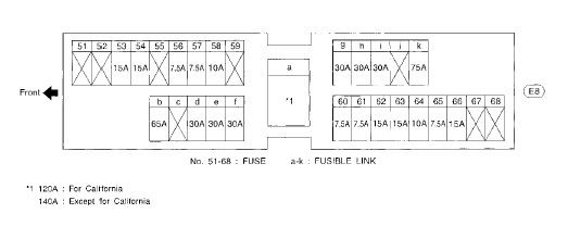
Check fuse #58 (10 amps) and replace if necessary.
The CPVCSV is easy to see and reach. It is located in the engine compartment, mounted to the top of the upper intake manifold. Notice the Vehicle Serial number stamped into the firewall. Put your finger on the third-from-last number. Move your finger three inches toward the radiator. That's the CPVCSV. It has one two-wire electrical connector and two vacuum hoses.
You may test the valve. This test procedure is performed with the engine off. Remove the electrical connector and both vacuum hoses. Fasten a length of clean rubber vacuum tubing to either nipple. Gently blow through the hose. The valve should be closed and it should be difficult or impossible to send air through the valve. Now use a pair of fused test leads to provide 12 volts to the electric terminals. The polarity doesn't matter. With the solenoid energized the valve should be open and it should be easy to send air through the valve.
0901
Diagnostic Trouble Code 0901 points to a problem with the Front Heated Oxygen Sensor, Right Bank. The right cylinder bank is also called the rear bank. It is cylinders 1,3,5.
The Front Heated Oxygen Sensors are installed in the Y-pipe, the part of the exhaust system which conveys exhaust gases from the exhaust manifolds to the Catalytic Converter. There is an Oxygen Sensor in each branch of the Y-pipe. These sensors produce a signal which varies with the concentration of oxygen in the exhaust gas, as compared to the outside air. This signal is sent to the Engine Control Module which uses it to control the fuel injection system.
DTC 0901 is detected when the current drawn by the heating element in the Oxygen Sensor is out of the normal range.
Possible causes include ...
- harness or connectors (the sensor circuit is open or shorted.)
- a defective Front Heated Oxygen Sensor (right bank).
The heated Oxygen Sensors have two components: a heating element and a sensing element. The heating element may be tested with an ordinary ohmmeter. This test is done with the engine off.
Follow the wires away from the Oxygen Sensor until you find the nearest electrical connector. Disconnect the connector. Viewed with the connector latch at the 12 o'clock position, there are three terminals. They are numbered 1-3, right to left. Be sure to measure the terminals in the connector half which is attached to the Oxygen Sensor, not the one which leads to the Engine Control Unit.
Measure the resistance between terminals 1 and 3.
The factory spec is 2.3-4.3 ohms at 77 degrees Fahrenheit.
Measure the resistance between terminals 1 and 2.
The reading should be infinity (no connection).
Measure the resistance between terminals 2 and 3.
The reading should be infinity (no connection).
If the resistance measurements are significantly different from the factory specifications the sensor is faulty and must be replaced.
If the resistance measurements meet the factory specifications the sensor may be good and the wiring is defective. You could exchange the two Front Heated Oxygen Sensors and reset the Engine Control Module. Then drive normally and expect the Malfunction Indicator Lamp to turn on again. If you still get DTC 0901 the wiring is faulty. If you get DTC 1001 the sensor is bad.
0902
Diagnostic Trouble Code 0902 points to a problem with the Rear Heated Oxygen Sensor Heater.
The malfunction is detected when the current in the Oxygen Sensor heater circuit is out of the normal range.
Possible causes include ...
- the electrical harnesses
- the connector
- the Oxygen Sensor heaters
You may test the heater with an ohmmeter. This test is done with the engine off.
Raise the car and support it on sturdy jackstands. Slide under and disconnect the connector. Viewed with the connector latch at the 12 o'clock position, there are four terminals. They are numbered 1-2, top row, right to left and 3-4, bottom row, right to left. Be sure to measure the resistances of the Oxygen Sensor, not the harness which leads to the Engine Control Unit.
Measure the resistance between terminals 1 and 4.
The factory spec is 2.3-4.3 ohms at 77 degrees Fahrenheit.
Measure the resistance between terminals 2 and each of the other terminals.
The reading should be infinity (no connection).
Measure the resistance between terminals 3 and each of the other terminals.
The reading should be infinity (no connection).
Check fuse #31 (15 amps) in the passenger cabin fuse block. That fuse block has three columns of fuses.
The left-most column contains fuses 1 - 11, numbered from bottom to top.
The middle column contains fuses 12 - 26, numbered from bottom to top.
The right-most column contains fuses 27 - 40, numbered from bottom to top.
The numbers are molded into the plastic fuse block. They are not easy to read. A flashlight will be helpful.
Diagnostic Trouble Code 0503 indicates a problem with the front Oxygen Sensor on the right cylinder bank. The right bank is also called the rear bank. It is cylinders 1,3,5. A normal signal sweeps back and forth between 0.2 volts and 0.8 volts. This malfunction was detected when the Engine Control Module received a signal from the sensor which was a constant value of approximately 0.3 volts.
Possible causes include ...
- Harness or connectors (the sensor circuit is open or shorted).
- Defective Oxygen Sensor
0504
Diagnostic Trouble Code 0504 points to a problem with the Automatic Transmission Communications line. Pulse signals are exchanged between the Engine Control Module and the Transmission Control Module to assure smooth shifting during hard acceleration or deceleration.
This malfunction is detected when the ECM continuously receives an incorrect voltage from the TCM. Possible causes include...
- Harness or connectors (The communications line circuit between the ECM and the TCM is open or shorted.)
- TCM
- Discharged or faulty battery
0505
No Failure Recorded/Detected
0510
Diagnostic Trouble Code 0510 points to a problem with the Rear Heated Oxygen Sensor. This sensor is mounted in the exhaust stream, just downstream of the Catalytic Converter. When the two Front Heated Oxygen Sensors are operating properly the Rear Heated Oxygen Sensor is not used for engine control operation. It is used to monitor the condition of the Catalytic Converter. If either or both Front Sensors fail the Engine Control Module uses the signal from the Rear Sensor to maintain a correct fuel/air mixture.
DTC 0510 is detected when the signal from the Rear Heated Oxygen Sensor does not reach the expected maximum voltage threshold value. The possible causes include ...
- Harness or connectors (the sensor circuit is open or shorted.)
- Rear Heated Oxygen Sensor
- Fuel pressure
- Fuel injectors
- Intake air leaks
0603 0604 0605 0606 0607 0608
If one cylinder is misfiring the problem is spark or fuel. A misfire due to a spark problem usually results in a Service Engine Soon light and one of these Diagnostic Trouble Codes:
0608 - Cylinder 1 misfire
0607 - Cylinder 2 misfire
0606 - Cylinder 3 misfire
0605 - Cylinder 4 misfire
0604 - Cylinder 5 misfire
0603 - Cylinder 6 misfire
You don't have any of these codes, and the engine smooths out at engine speeds greater than 1000 rpm, so let's assume the problem is with fuel delivery.
I believe one of your fuel injectors is not performing properly. There are two tests the home mechanic can make, the sound test and the resistance test.
Sound test...
This test is performed with the engine idling. Use a mechanic's
s***hoscope or a length of rubber vacuum hose, and listen to each injector.
All injectors should sound alike. If you find one which makes a different
sound (or no sound at all) you have found a problem.
Resistance test...
This test is performed with the engine off. Use an ohmmeter to measure the
resistance of each injector. This does not require removing the injectors.
I don't know the correct resistance value for the injectors on your model,
but they are typically a low number such as 16 ohms. The important thing
is they should all be equal. If you find one injector with substantially
higher resistance than the others, it is bad. If you find one with zero
ohms (short circuit) that is truly unfortunate, because the injector is bad
and it may also have damaged the Engine Control Module (the computer)
because of excessive current drain.
Measuring the resistance of the front bank of cylinders is easy because the
injectors are in plain view. Disconnect the injector electrical connector
for cylinder #2, measure the resistance, reconnect the connector. Repeat
for the cylinders #4 and #6.
Measuring the resistance of the rear bank of cylinders is almost as easy,
but it is difficult to reach the injectors. The resistance may be measured
at a conveniently located electrical connector. Notice the largest,
thickest electrical harness at the top of the engine. This is the Engine
Control Harness and it is shaped like a U, with the open top of the U at the
driver's side of the car. The U has two corners. Look at the corner
nearest the passenger seat. Just inside that corner you will find an 8-pin
electrical connector. This is connector F131. Disconnect this
connector. Now look at the male part, the connector half with the pins
exposed. They are arranged in two rows of four pins.
The pins are numbered 1 - 4 (top row) and 5 - 8 (bottom row).
Measure the resistance of:
- injector #1 between pins 1 and 2.
- injector #3 between pins 1 and 6.
- injector #5 between pins 1 and 5.
Be sure to measure the PINS, not the female receptacles.
The dealer's shop is equipped with high-tech diagnostic instruments. These are wonderful devices but they are expensive and the dealer has to recover his cost by charging you for diagnostic time. Sometimes the home mechanic can do legitimate diagnostic work with nothing more than a ohmmeter and a
rubber tube.
To Test Ignition Coils:
With the ignition off, disconnect the electrical connector from the ignition coil. Connect the positive (+) probe of an ohmmeter to terminal no. 1 and the negative (-) probe to terminal no. 2 of the coil connector - the meter should indicate infinite resistance. Reverse the meter leads ( negative probe to terminal no. 1 and positive probe to terminal no.2) - the continuity should be indicated, but not zero ohms. If the results are not as specified, replace the coil.
Connect an ohmmeter between the secondary terminal ( the one that the spark plug connects to) and terminal no. 1 - the meter should indicate infinite resistance. If not, replace the coil.
Note - Ohm meter to test coils is not the most reliable way. Some peoples’ coils tested perfectly, but they still misfired.
0701
http://forums.maxima.org/showthread....highlight=0701
0702
Diagnostic Trouble Code 0702 points to a problem with the three-way Catalytic Converter.
The Cat is one of the principal components of the emissions control system. The Engine Control Module monitors the signals from the two front Oxygen Sensors and the one rear Oxygen Sensor. The signal frequency of each sensor indicates something about the condition of that sensor. A comparison of the frequency of the front sensors with the rear sensor indicates something about the condition of the Cat.
This malfunction was detected when the ratio of the signal frequency from the right bank front Oxygen Sensor to the signal frequency of the rear Oxygen Sensor exceeded a critical threshold value. This indicates that the Cat does not have enough oxygen storage capacity. The right cylinder bank is also called the rear bank. It is cylinders 1,3,5. Possible causes of this DTC include ...
- Three-way catalyst
- Exhaust tube
- Intake air leaks
- Fuel injectors
- Spark plugs
- Ignition timing
0703
Diagnostic Trouble Code 0703 points to a problem with the three-way Catalytic Converter.
The Cat is one of the principal components of the emissions control system. The Engine Control Module monitors the signals from the two front Oxygen Sensors and the one rear Oxygen Sensor. The signal frequency of each sensor indicates something about the condition of that sensor. A comparison of the frequency of the front sensors with the rear sensor indicates something about the condition of the Cat.
This malfunction was detected when the ratio of the signal frequency from the left bank front Oxygen Sensor to the signal frequency of the rear Oxygen Sensor exceeded a critical threshold value. This indicates that the Cat does not have enough oxygen storage capacity. Possible causes include ...
- Three-way catalyst
- Exhaust tube
- Intake air leaks
- Fuel injectors
- Spark plugs
- Ignition timing
0704
Diagnostic Trouble Code 0704 points to a problem with the Evaporative Emission Control System Pressure Sensor. The EVAPCSPS is installed in the purge line. The sensor detects the pressure inside the purge line and sends a signal to the Engine Control Module. The signal voltage is directly proportional to pressure. The EVAPCSPS is not directly used to control engine operating parameters. It is used only to evaluate EVAP performance. Therefore a car with DTC 0704 should start and run normally.
The EVAPCSPS is located on the underside of the car near the left rear wheel. It is mounted near, but not directly on, the EVAP canister.
This malfunction is detected when the EVAPCSPS sends an out-of-range voltage signal to the Engine Control Module.
Possible causes include...
- harness or connectors (The EVAPCSPS circuit is open or shorted.)
- bad EVAPCSPS
- EVAP Canister Vent Control Valve is stuck open
- rubber hose connected to EVAPCSPS is clogged, bent, kinked, disconnected, or improperly connected
- EVAP Canister is damaged or saturated with water
- rubber hose from EVAP Canister Vent Control Valve to the water separator
- EVAP Canister Purge Volume Control Solenoid Valve
0705
Diagnostic Trouble Code 0705 points to a problem with the Evaporative Emission Control System.
This malfunction is detected when the EVAP control system has a leak or the EVAP control system does not operate properly. (EVAP = EVAPorative emissions.)
Possible causes include...
- incorrect fuel tank vacuum relief valve
- incorrect fuel filler cap
- fuel filler cap vent remains open or fails to close
- foreign matter caught in fuel filler cap
- a leak in the line between the intake manifold and the
EVAP Canister Vacuum Control Valve
- foreign matter caught in the EVAP CVCV
- leaks in the EVAP canister or fuel tank
- leaks in the EVAP purge line (pipe and rubber tube)
- EVAP purge line rubber tube bent
- blocked or bent rubber tube to EVAP control system pressure sensor
- loose or disconnected rubber tube
- EVAP CVCV and circuit
- EVAP Canister Purge Volume Control Solenoid Valve and circuit
- absolute pressure sensor
- tank fuel temperature sensor
- MAP/BARO switch solenoid valve and circuit
- blocked or bent rubber tube to MAP/BARO switch solenoid valve
- O-ring of EVAP CVCV is missing or damaged
- water separator
- EVAP canister saturated with water
- EVAP control system pressure sensor
- refueling EVAP vapor cut valve
- ORVR system leaks
This is a "jackpot" DTC. It points to so many things you don't know what to check. It is often combined with another DTC which is more specific and therefore more helpful.
0707
Your Maxima engine is OBD-2 compliant. All Diagnostic Trouble Codes are four digits, with the first is always 0 or 1. Therefore your "77" is actually "0707" which points to the rear Oxygen Sensor.
Your Maxima has three Oxygen Sensors. Two are front sensors, mounted in
the Y-pipe between the exhaust manifolds and the Catalytic Converter. One
is a rear sensor, mounted in the exhaust pipe downstream of the Cat.
When both front Oxygen Sensors are operating normally the rear sensor serves only to keep tabs on the Catalytic Converter. That's the reason your engine is running well. The Engine Control Module (the computer) is not using the signal from the rear sensor to control engine management functions.
For more information about Oxygen Sensors go to
http://www.volksparts.com/o2sensors.htm
For specific information about replacing Oxygen Sensors on your Maxima see
the Chilton manual (page 4-13) or the Haynes manual (page 6-14).
In a different thread SprintMax said he got a great price on a replacement factory Oxygen Sensor from Vester Nissan. He didn't give a location or contact information. Perhaps he was referring to Vester Nissan of Clinton NC, 1-800-572-2005.
0801
Diagnostic Trouble Code 0801 points to a problem with the Vacuum Cut Valve Bypass Valve. The malfunction is detected when an improper voltage signal is sent to the Engine Control Module through the VCVBV. The possible causes of this problem include a defect with the wiring or electrical connector, or with the valve itself. The VCVBV is located under the car, near the rear left tire. It is near the Evaporative Emission Canister but not mounted directly on it.
The VCVBV is a solenoid-controlled air valve. You may remove it from the vehicle and perform a bench test. There are two air hose nipples on the valve. Fasten a length of clean rubber vacuum tubing to either nipple. Gently blow through the hose. The valve should be closed and it should be difficult or impossible to send air through the valve. Now use a pair of fused test leads to provide 12 volts to the electric connector. The polarity doesn't matter. With the VCVBV solenoid energized the valve should be open and it should be easy to send air through the valve.
0802
http://forums.maxima.org/showthread....highlight=0802
0803
http://forums.maxima.org/showthread.php?t=58352
0804
Diagnostic Trouble Code 0804 is detected when the signal from the Transmission Control Module is not sent to the Engine Control Module. The factory service manual identifies these possible causes:
- Harness or connectors (the communications line circuit between ECM and TCM is open or shorted.)
- TCM
- Weak or dead battery
0806
http://forums.maxima.org/search.php?...der=descending
0807
Diagnostic Trouble Code 0807 does not appear in the '99 Maxima factory service manual, and that is my principal information source. I'll tell what I know about the '99 Maxima EVAP Canister Purge Volume Control Solenoid Valve. This information may or may not apply to your Maxima.
The Evaporative Emission (EVAP) Canister Purge Volume Control Solenoid Valve uses an on/off duty cycle to control the flow of fuel vapor from the EVAP canister. Diagnostic Trouble Code 1008 is set when the Engine Control Module (the computer) detects an improper signal through the valve. The problem is likely to be in the electrical wiring, harness, or the valve itself.
Check fuse #58 (10 amps) and replace if necessary.
The CPVCSV is easy to see and reach. It is located in the engine compartment, mounted to the top of the upper intake manifold. Notice the Vehicle Serial number stamped into the firewall. Put your finger on the third-from-last number. Move your finger three inches toward the radiator. That's the CPVCSV. It has one two-wire electrical connector and two vacuum hoses.
You may test the valve. This test procedure is performed with the engine off. Remove the electrical connector and both vacuum hoses. Fasten a length of clean rubber vacuum tubing to either nipple. Gently blow through the hose. The valve should be closed and it should be difficult or impossible to send air through the valve. Now use a pair of fused test leads to provide 12 volts to the electric terminals. The polarity doesn't matter. With the solenoid energized the valve should be open and it should be easy to send air through the valve.
0901
Diagnostic Trouble Code 0901 points to a problem with the Front Heated Oxygen Sensor, Right Bank. The right cylinder bank is also called the rear bank. It is cylinders 1,3,5.
The Front Heated Oxygen Sensors are installed in the Y-pipe, the part of the exhaust system which conveys exhaust gases from the exhaust manifolds to the Catalytic Converter. There is an Oxygen Sensor in each branch of the Y-pipe. These sensors produce a signal which varies with the concentration of oxygen in the exhaust gas, as compared to the outside air. This signal is sent to the Engine Control Module which uses it to control the fuel injection system.
DTC 0901 is detected when the current drawn by the heating element in the Oxygen Sensor is out of the normal range.
Possible causes include ...
- harness or connectors (the sensor circuit is open or shorted.)
- a defective Front Heated Oxygen Sensor (right bank).
The heated Oxygen Sensors have two components: a heating element and a sensing element. The heating element may be tested with an ordinary ohmmeter. This test is done with the engine off.
Follow the wires away from the Oxygen Sensor until you find the nearest electrical connector. Disconnect the connector. Viewed with the connector latch at the 12 o'clock position, there are three terminals. They are numbered 1-3, right to left. Be sure to measure the terminals in the connector half which is attached to the Oxygen Sensor, not the one which leads to the Engine Control Unit.
Measure the resistance between terminals 1 and 3.
The factory spec is 2.3-4.3 ohms at 77 degrees Fahrenheit.
Measure the resistance between terminals 1 and 2.
The reading should be infinity (no connection).
Measure the resistance between terminals 2 and 3.
The reading should be infinity (no connection).
If the resistance measurements are significantly different from the factory specifications the sensor is faulty and must be replaced.
If the resistance measurements meet the factory specifications the sensor may be good and the wiring is defective. You could exchange the two Front Heated Oxygen Sensors and reset the Engine Control Module. Then drive normally and expect the Malfunction Indicator Lamp to turn on again. If you still get DTC 0901 the wiring is faulty. If you get DTC 1001 the sensor is bad.
0902
Diagnostic Trouble Code 0902 points to a problem with the Rear Heated Oxygen Sensor Heater.
The malfunction is detected when the current in the Oxygen Sensor heater circuit is out of the normal range.
Possible causes include ...
- the electrical harnesses
- the connector
- the Oxygen Sensor heaters
You may test the heater with an ohmmeter. This test is done with the engine off.
Raise the car and support it on sturdy jackstands. Slide under and disconnect the connector. Viewed with the connector latch at the 12 o'clock position, there are four terminals. They are numbered 1-2, top row, right to left and 3-4, bottom row, right to left. Be sure to measure the resistances of the Oxygen Sensor, not the harness which leads to the Engine Control Unit.
Measure the resistance between terminals 1 and 4.
The factory spec is 2.3-4.3 ohms at 77 degrees Fahrenheit.
Measure the resistance between terminals 2 and each of the other terminals.
The reading should be infinity (no connection).
Measure the resistance between terminals 3 and each of the other terminals.
The reading should be infinity (no connection).
Check fuse #31 (15 amps) in the passenger cabin fuse block. That fuse block has three columns of fuses.
The left-most column contains fuses 1 - 11, numbered from bottom to top.
The middle column contains fuses 12 - 26, numbered from bottom to top.
The right-most column contains fuses 27 - 40, numbered from bottom to top.
The numbers are molded into the plastic fuse block. They are not easy to read. A flashlight will be helpful.
07-25-2003, 10:25 AM
#5
0903
Diagnostic Trouble Code 0903 indicates a problem with the Evaporative Emission (EVAP) Canister Vent Control Valve or its associated electric circuit.
This part is used by the Engine Control Module to perform the fuel system leak test. Since it is used only for self-diagnosis your engine will run perfectly well despite the dashboard Malfunction Indicator Lamp.
The EVAP canister and this valve are located under the car, near the rear left tire. You might check to make sure all the electrical connectors in that area are secure.
There's no telling how expensive the repair will be, because no definite diagnosis has been made. Maybe you just have to re-plug a loose connector. Since the EVAP system is part of the emissions control system you might have warranty coverage.
0904
http://forums.maxima.org/search.php?...der=descending
0905
http://forums.maxima.org/showthread.php?t=78486
0908
http://forums.maxima.org/showthread....highlight=0908
1001
http://forums.maxima.org/showthread....highlight=1001
1003
http://forums.maxima.org/showthread....highlight=1003
1005
1005 is EGRC Solenoid valve
The majority of my information about Diagnostic Trouble Codes comes from my '99 Maxima factory service manual. Unfortunately, DTC 1005 is not in that book. Starting in '99 the Maxima engine uses a step-motor type of EGR valve and with that change, the DTCs changed.
The Chilton and Haynes manuals provide a little information about the EGR Solenoid Valve.
The test procedure for this part is found in the Chilton repair manual (page 4-11) and the Haynes repair manual (page 6-20). Test the valve and replace if necessary.
This malfunction is not an emergency but should be resolved fairly soon (7-10 days). An inoperative EGR valve may result in engine pinging and a variety of driveability complaints.
1008
The Evaporative Emission (EVAP) Canister Purge Volume Control Solenoid Valve uses an on/off duty cycle to control the flow of fuel vapor from the EVAP canister. Diagnostic Trouble Code 1008 is set when the Engine Control Module (the computer) detects an improper signal through the valve. The problem is likely to be in the electrical wiring, harness, or the valve itself.
Check fuse #58 (10 amps) and replace if necessary.
The CPVCSV is easy to see and reach. It is located in the engine compartment, mounted to the top of the upper intake manifold. Notice the Vehicle Serial number stamped into the firewall. Put your finger on the third-from-last number. Move your finger three inches toward the radiator. That's the CPVCSV. It has one two-wire electrical connector and two vacuum hoses. It is directly above the ignition coil connector for cylinder #5 and has to be removed in order to replace the #5 coil or spark plug.
You may test the valve. This test procedure is performed with the engine off. Remove the electrical connector and both vacuum hoses. Fasten a length of clean rubber vacuum tubing to either nipple. Gently blow through the hose. The valve should be closed and it should be difficult or impossible to send air through the valve. Now use a pair of fused test leads to provide 12 volts to the electric terminals. The polarity doesn't matter. With the solenoid energized the valve should be open and it should be easy to send air through the valve.
http://www.jcn.net/mwest/evappage.htm
1101
http://forums.maxima.org/showthread....highlight=1101
1102
http://forums.maxima.org/showthread....highlight=1102
1103 1104 1105 1106
Since DTCs 1103 to 1106 deal with the transmission, there is info on the 1106 DTC. Everywhere you see "4th gear", simply substitute "1st gear".
Diagnostic Trouble Code 1106 means "Automatic Transmission 4th gear malfunction."
This malfunction is detected when the automatic transmission does not shift into fourth gear or the torque converter clutch does not lock up as instructed by the Transmission Control Unit. The factory service manual lists these possible
causes...
- Shift solenoid A
- Shift solenoid B
- Overrun clutch solenoid valve
- Line pressure solenoid valve
- Each clutch
- Hydraulic control circuit
- Torque converter clutch solenoid valve
You can do some troubleshooting without opening the automatic transmission. Find the harnesses which emanate from the transaxle. One of them terminates in a brown plastic connector with eight pins. This is connector F42, located (approximately) above the transaxle case and below the black plastic engine air intake ductwork. With the engine off, disconnect F42. You want to measure the transmission side of F42. Hold the connector such that the plastic latch is at the top. You should now see two rows of four terminals. These are numbered (top row, left to right) 1 - 4, and (bottom row, left to right) 5 - 8. Make resistance measurements between a clean ground and the following terminals:
#1, Shift solenoid B, 20 - 40 ohms.
#2, Shift solenoid A, 20 - 40 ohms.
#3, Overrun clutch solenoid valve, 20 - 40 ohms.
#4, Line pressure solenoid valve, 2.5 - 5 ohms.
#5, Torque converter clutch solenoid valve, 10 - 20 ohms.
There is also a "bench test" procedure for testing these solenoids with a 12 volt supply such as a car battery. However, this requires removal of the shift solenoid valve assembly. I don't know if you want to get involved with that.
1107
Diagnostic Trouble Code P0744(1107) indicates a problem with the Solenoid Valve Lock-up Function. This malfunction is detected when the A/T does not shift into fourth gear position or the torque converter clutch does not lock up as instructed by the Transmission Control Module. The electric circuit is good but the A/T failed to lock up. Possbile causes include...
- Torque converter clutch solenoid valve
- Each clutch
- Hydraulic control circuit.
DTC P0744 is entirely consistent with P0734. It's no surprise to find both codes set. They are both warning of the same problem, so whatever fixes one will most likely fix the other.
1108
http://forums.maxima.org/showthread....highlight=1108
1201
http://forums.maxima.org/search.php?...der=descending
1203
http://forums.maxima.org/search.php?...der=descending
1204
http://forums.maxima.org/showthread....highlight=1204
1205
http://forums.maxima.org/search.php?...der=descending
1206
Diagnostic Trouble Code 1206 points to a problem with the TPS.
The Throttle Position Sensor detects the throttle valve position and sends a signal to the Transmission Control Module.
The Throttle Position Switch consists of a Wide Open Throttle position switch and a closed throttle position switch. The WOT switch sends a signal to the TCM when the throttle is open at least 1/2 of the WOT position. The closed throttle position switch sends a signal to the TCM when the throttle is fully closed.
The Sensor and Switch are integrated into one unit designated TPS.
This malfunction may be detected when the TCM receives an excessively low or high voltage from the sensor.
Possible causes include ...
- Harness or connectors (the throttle position sensor is open or shorted.)
- faulty Throttle Position Sensor
- faulty Throttle Position Switch
1207
http://forums.maxima.org/search.php?...der=descending
1208
http://forums.maxima.org/search.php?...der=descending
1302
http://forums.maxima.org/showthread....highlight=1302
1305
Fuel Pump Control Module
1308
Cooling Fan
All searching has been done by KevLo911
02-21-2004, 06:48 AM
#6
These are all the Code Scanner Codes Converted from the Haynes Manual
Scan Tool Trouble Code --- Check Engine Light flash code
P0000 --- 0505
P0100 --- 0102
P0105 --- 0803
P0110 --- 0401
P0115 --- 0103
P0120 --- 0403
P0125 --- 0908
P0130 --- 0307
P0130 --- 0503
P0131 --- 0411
P0132 --- 0410
P0133 --- 0409
P0134 --- 0412
P0135 --- 0901
P0136 --- 0707
P0137 --- 0511
P0138 --- 0510
P0139 --- 0707
P0140 --- 0512
P0141 --- 0902
P0150 --- 0303
P0151 --- 0308
P0152 --- 0415
P0153 --- 0414
P0154 --- 0413
P0155 --- 1001
P0157 --- 0314
P0158 --- 0313
P0159 --- 0708
P0160 --- 0315
P0161 --- 1002
P0170 --- 0706
P0171 --- 0115
P0172 --- 0114
P0173 --- 0806
P0174 --- 0210
P0175 --- 0209
P0180 --- 0402
P0300 --- 0701
P0301 --- 0608
P0302 --- 0607
P0303 --- 0606
P0304 --- 0605
P0305 --- 0604
P0306 --- 0603
P0325 --- 0304
P0335 --- 0802
P0340 --- 0101
P0400 --- 0302
P0402 --- 0306
P0403 --- 0515
P0420 --- 0702
P0430 --- 0703
P0440 --- 0705
P0443 --- 0807
P0443 --- 1008
P0446 --- 0903
P0450 --- 0704
P0500 --- 0104
P0505 --- 0205
P0510 --- 0203
P0600 --- 0504
P0605 --- 0301
P0705 --- 1003
P0705 --- 1101
P0710 --- 1208
P0720 --- 1102
P0725 --- 1207
P0731 --- 1103
P0732 --- 1104
P0733 --- 1105
P0734 --- 1106
P0740 --- 1204
P0744 --- 1107
P0745 --- 1205
P0750 --- 1108
P0755 --- 1201
P1105 --- 1302
P1148 --- 0307
P1168 --- 0308
P1220 --- 1305
P1320 --- 0201
P1335 --- 0407
P1336 --- 0905
P1400 --- 1005
P1401 --- 0305
P1402 --- 0514
P1440 --- 0213
P1441 --- 0801
P1444 --- 0214
P1445 --- 1008
P1446 --- 0215
P1447 --- 0111
P1448 --- 0309
P1490 --- 0801
P1491 --- 0311
P1492 --- 0807
P1493 --- 0312
P1605 --- 0804
P1705 --- 1206
P1706 --- 1003
P1760 --- 1203
P1900 --- 0208
P1900 --- 1308
0309
Evap Cannister Vent Control Valve-Trace vacuum hard lines to make sure that there are no leaks to the evap cannister.
Reference FSM EC-23 for a diagram.
0105
The absolute pressure sensor is located to the MAP/BARO switch solenoid valve by a hose. The sensor detects abient barometric pressure and intake manifold pressure respectively, and modifies the voltage signal from the ECM.
FSM pages EC 117-126
I would check to see if the sensor is plugged in and the hose is connected
a picture of it is seen in post #25
http://forums.maxima.org/showpost.ph...6&postcount=25
P0440 and/or P1448
The P0440 is a generic EVAP system leak. The P1448 is a manufacturer specific code for the charcoal canister vent valve stuck open. The charcoal canister is located behind the left rear tire. It's a largish black box with a few hoses running to it.
First, check all of these hoses to make sure none or torn or otherwise damaged. If they check out, disconnect these hoses and the electrical connection with a pair of pliers. Then, remove the three screws that hold the box to the car, then push the rear bracket out of the way to remove it. With the box out, take off the two screws that hold the purge valve to the box. It takes a bit of force to remove the valve even with the screws out. Be firm, but don't break it.
Next, take some brake cleaner and spray through one of the holes so it flows out the other. Hose it for a good 10 seconds or so, then spray some silicone spray through it to lubricate it. Install the valve back on the box, put the box back in the car and reconnect the hoses and wire connector.
With the car back together, clear the codes on the ECU and you should be good. If this doesn't work, double check all the lines in that area and if all else fails, you might need a new canister vent valve. You should be able to test the valve by applying 12 volts to the two terminals. A replacement valve runs about $120 from a dealer, so do your best to fix your old one first.
OMG The battery and brake light came on at the same time
ALT fuse has blown. It is located under the hood in the fuse box near the battery. It can alos mean the voltage has dropped under 10v. In most cases this means your Alternator is dead/shorted out. Replace the fuse when you replace the alternator.
OMG MY AIRBAG LIGHT IS ON!!!
Airbag Light Fix (revised)
IF YOUR AIRBAG LIGHT IS FLASHING WHILE YOU DRIVE 9 times out of 10 it is the passenger seat side air bag...the one that is inside of the seat...what you need to do is the following:
Open your door and first locate the button on pillar A....this little button is the drivers door switch and when the door is closed the button is pressed in making the car know that the door is actually closed....it is a small button with black rubber surrounding it. Once you locate it, turn your key to the ON position....DO NOT start the car...simply turn the power on so the engine light, battery and everything else is lit without engaging the ignition. Then with the key in the ON position press the drivers door switch at least 10 times within 10 seconds with your finger: in and out in and out fast......then once you have done that turn your key to the OFF position....when i did this I found it easy to turn the key half way between where you take it out and half way between ACC so nothing should be getting power...not even the radio but you should also not be able to pull the key out. Then close your door and with the key in that same position, between taking it out and ACC, start the car by turning it towards the ignition. This means don't take the key outta the ignition the whole time.
If you have a 99 9/10 it is the passenger SEAT airbag....the one that is actually in the seat and Nissan will try to tell you it is faulty but by doing this you will engage the system so it will work again. I know people that have had the seat air bag repaired and then the light has come on within a year. If it was the airbag that was in the dash I would say get it fixed but with it being a seat air bag even if it doesn't work the rest of the system will. Same thing happened to me and I got it diagnosed luckily for free at the dealership but then did the thing above and it hasn't come back on in over a year and a half. A lot of times they said it could be caused by a passenger having their feat under the seat where the air bag components are.
Print this out and GO DO IT NOW!!!! It works.....mine went on in March 2004 and I was told by Nissan I needed a new passenger side SEAT airbag....the side curtain on that is INSIDE the actual seat of your car if you have it. Nissan said it was VERY common and it is faulty.....amazingly they even had some on-hand....follow this how -to!
Last edited by phenryiv1; 04-30-2008 at 06:29 AM.
08-30-2008, 06:47 PM
#7
Got fed up with people *****ing about undefined codes in the existing 'decoder', so over the last few days I made this:
pmohr's A32 CEL Decoder
It's got every code from each year's respective FSM, including any AT faults that set a P or MIL code. Most of the emissions (and most notably, the O2 codes) are year specific, so be sure to select the correct year at the top.
If it comes up saying 'code not found', then either you typed in the wrong code number (typo or misread from the CEL), or it's possible, though very unlikely that the code exists but is not listed in the FSM.
In the 'Code' input, either enter the 4 digit code you get from the flashing CEL (0304 for KS, 0701 for Multiple Cylinder Misfire, etc).
You can also enter OBD-II P-codes (P0325 for KS, P0300 for Multiple Cylinder Misfire, etc) but be sure you include the P.
If you enter some OBD-II codes without the P, you'll get incorrect results. For example, 0505 means nothing is wrong, but P0505 is an IACV fault.
You can link to each individual search result, either through the address bar in your browser or via the 'Link to this page' link at the bottom of the results.
For example, knock sensor code for a '96, or swirl control valve for a '99.
I encourage as many people as possible to give it a try, by all means PM me if you find any typos, incorrect information, etc. I want to make this thing perfect so we have no more 'undefined code' posts.
Last edited by Kevlo911; 06-29-2009 at 11:50 AM.
03-15-2009, 12:00 PM
#8
Added a small section to the decoder, it's BBcode you can paste in your thread; has the DTC 'P' code, small description, and the image from the FSM.
Ex:
Code: P0443 | Description: Purge Volume Control Valve
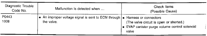
Ex:
Code: P0443 | Description: Purge Volume Control Valve

Thread
Thread Starter
Forum
Replies
Last Post
maxinout93
5th Generation Maxima (2000-2003)
3
08-20-2015 02:17 AM